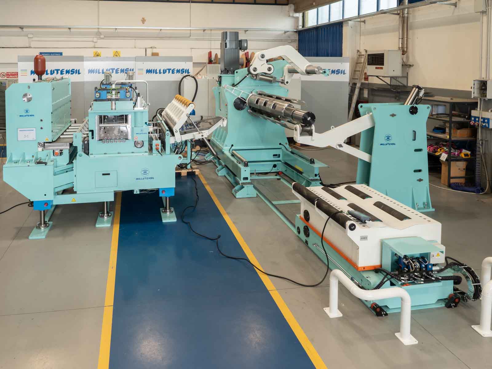
COMPACT COIL LINE WITH SERVO REEL TECHNOLOGY
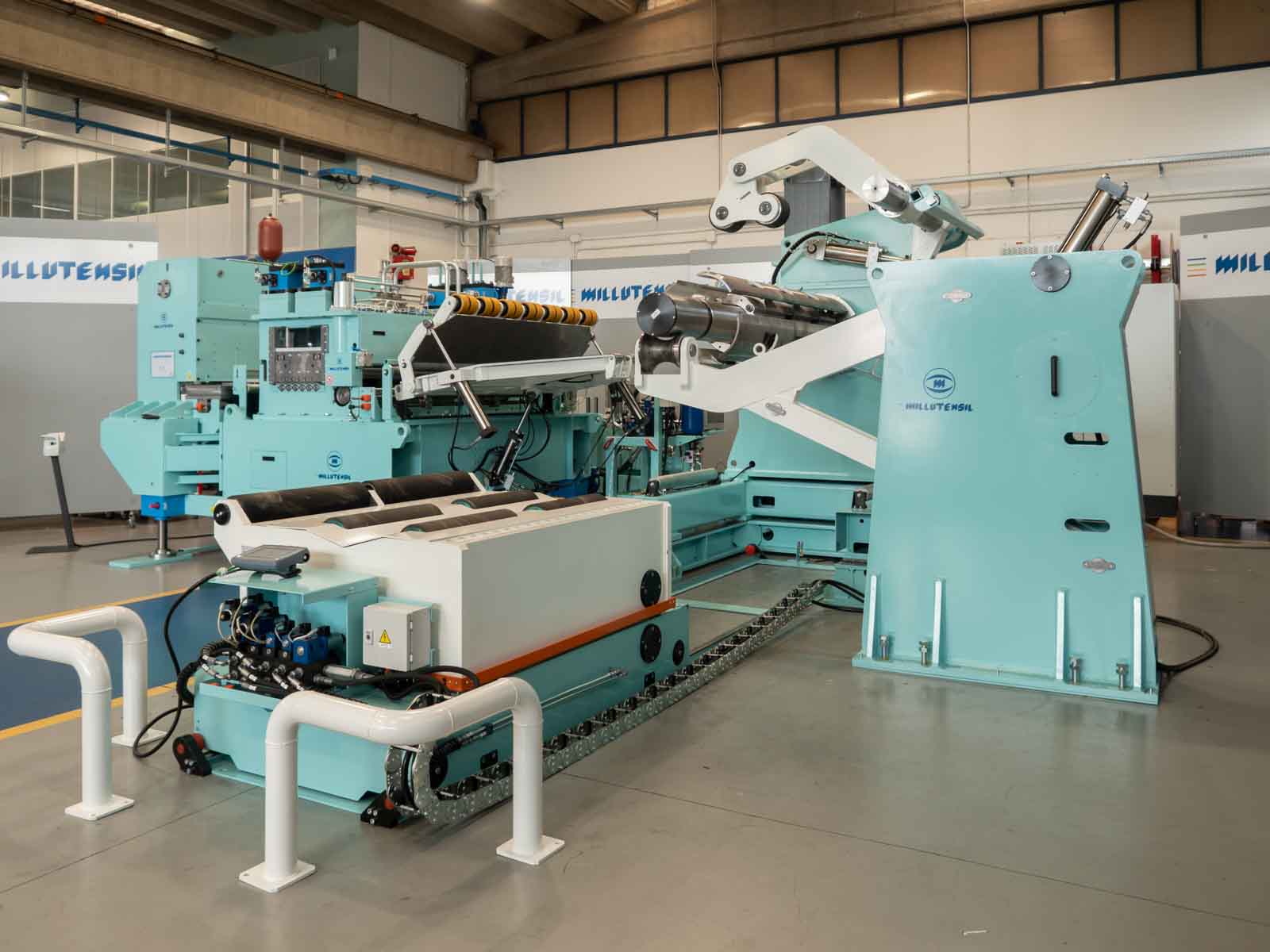
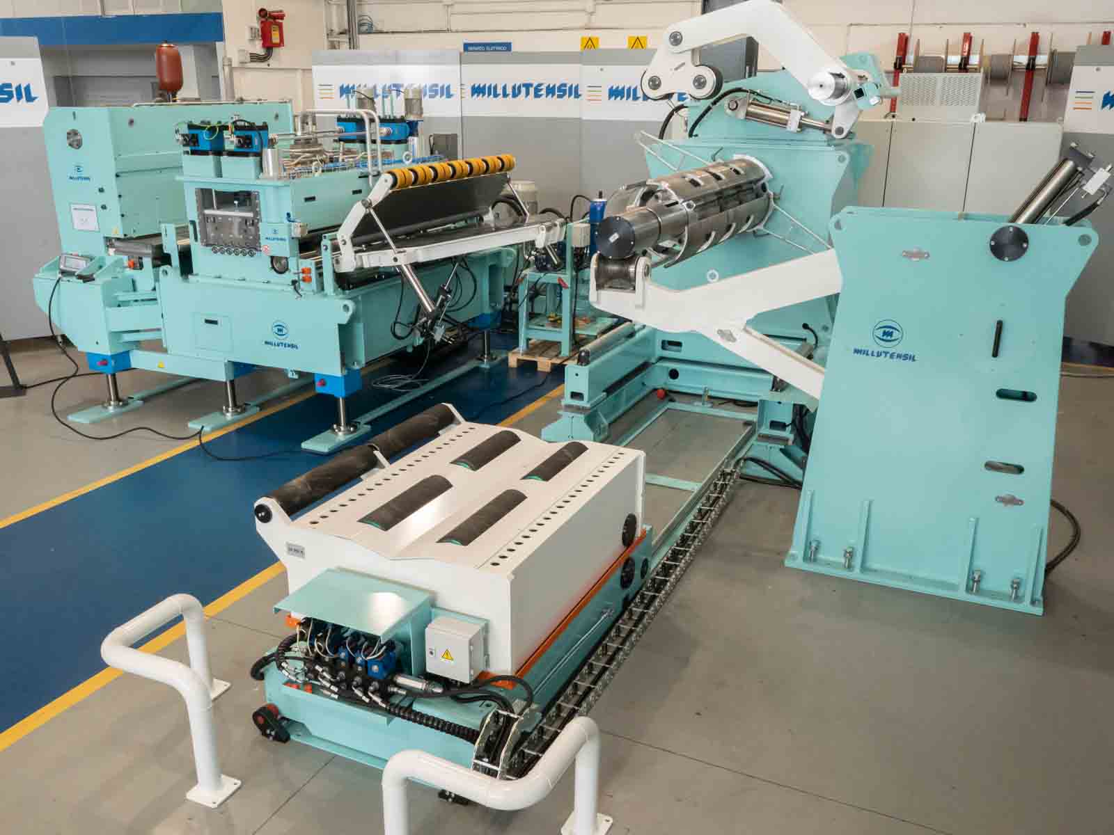
An extremely interesting solution: the compact coil line, designed for high-strength materials and significant thicknesses, leveraging servo reel technology. Thanks to this innovative and advanced technology, it is possible to keep the coil compact and work the material in a synchronized manner, always ensuring its compactness.
| Parameter | Value |
| Decoiler capacity | 20,000 kg |
| Maximum outer diameter of coil | 1,800 mm |
| Inner diameter of coil | 480-620 mm |
| Maximum width | 2,000 mm |
| Maximum thickness | 4 mm |
| Material type | High Strength Steel [RM]/DP 600/1000 N/MPa |
| Max step | 1,300 mm |
| Press strokes | 20 spm |
| Unwinding direction | From the top or bottom |
| Working modality | transfer or progressive die |
virtual 3D
Press the mouse and move to explore the line from all angles. Use the scroll wheel to zoom in.
DECOILER
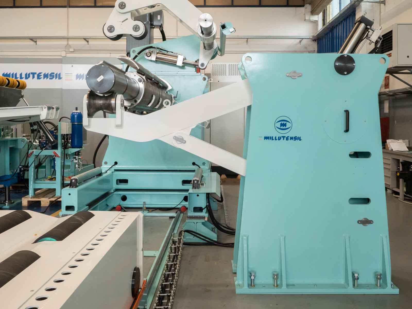
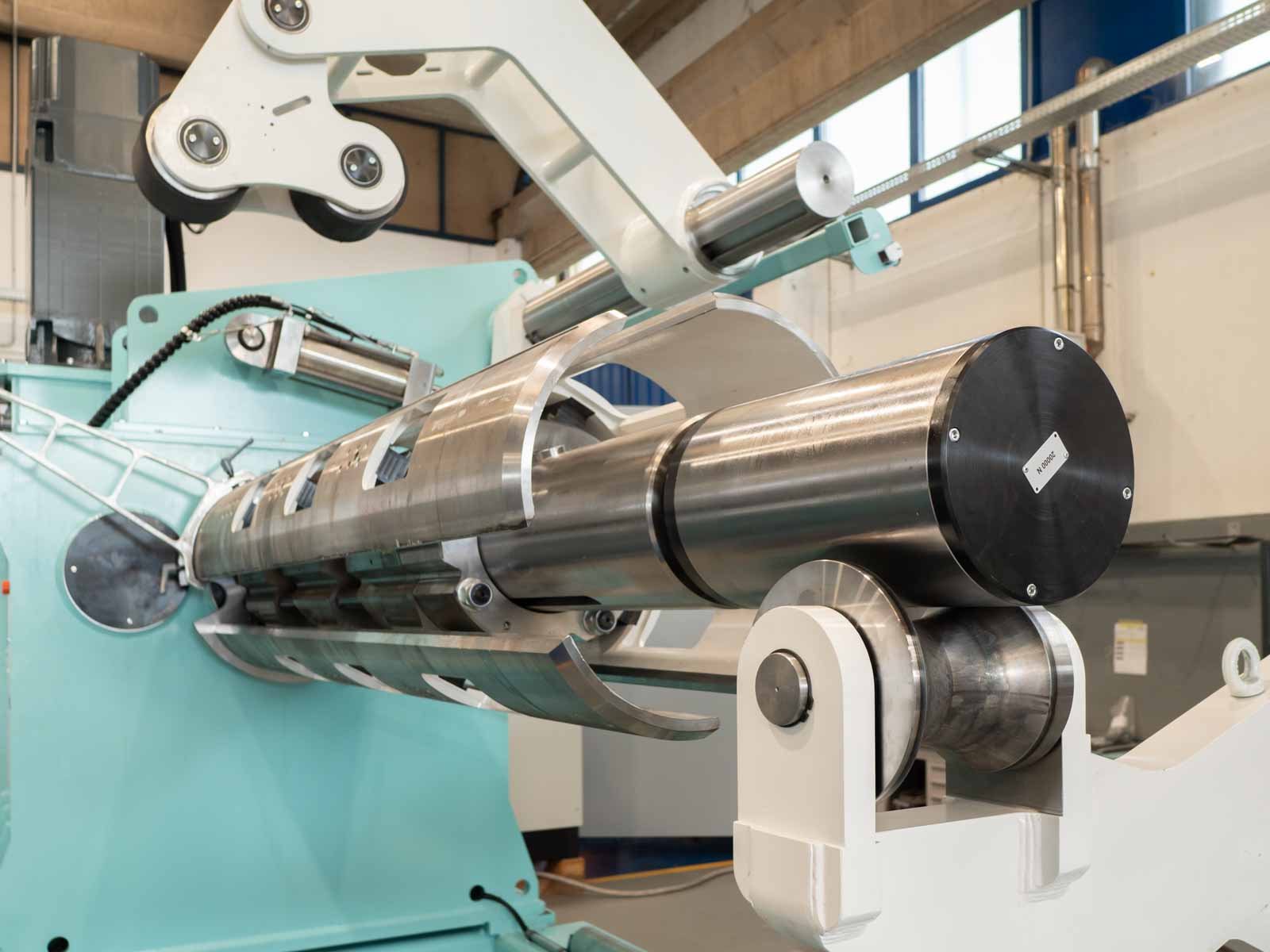
The decoiler assembly features a sturdy steel frame, extensively welded for durability and stability, capable of accommodating heavy loads. The spindle shaft is supported by double roller bearings, ensuring even weight distribution and smooth rotation. Hydraulic wedges are employed for mandrel expansion and closure, guaranteeing precise and reliable material clamping.
Lateral translation is motorized, facilitated by a specially designed slide for precise tape alignment. A press arm, located at the top of the coil unwinder, is operated by a hydraulic cylinder to securely hold materials in place during insertion. Polyurethane-coated wheels provide gentle traction on the material surface, preventing damage during movement, controlled conveniently from the control panel.
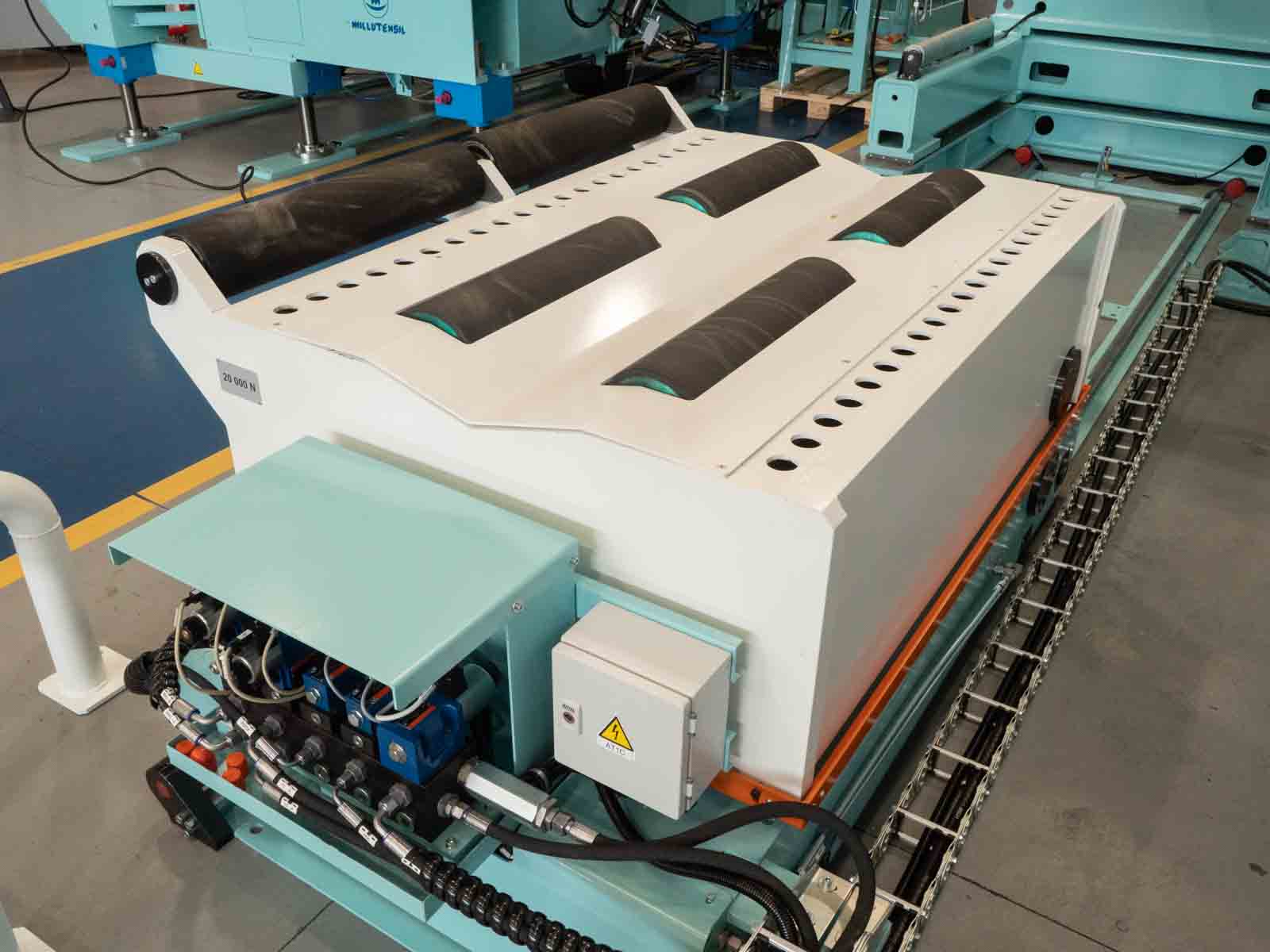
Containment brackets are in place to secure coil stability during unwinding. The mobile loading cradle is constructed with a robust, welded steel frame, featuring a floor-mounted motorized translation system for coil retrieval from storage and transport to the unwinder. The hydraulic lifting is appropriately sized to allow precise positioning of coils of varying diameters on the unwinder mandrel. Additionally, V-shaped coil support on the cradle prevents lateral rolling, while lateral containment poles ensure coils remain securely fixed during translation, preventing potential falls or material damage.
The mandrel support is an essential component integrated at the base of the reel. It consists of an arm moved by a hydraulic cylinder, supporting the mandrel at its end. This is crucial to prevent bending of the mandrel during operation, ensuring smooth and consistent pulling of the material throughout its width. Thanks to this system, it’s possible to exert even traction across the material’s entire width, ensuring precise and high-quality processing.
FEEDING STRAIGHTENER MACHINE
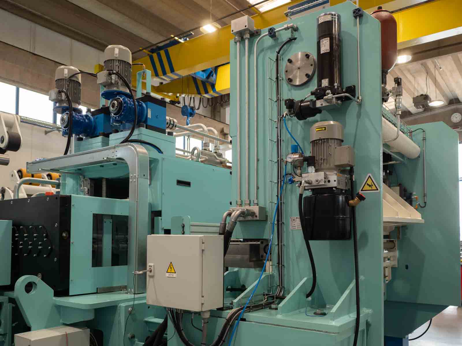
The feeding straightener machine features an openable head operated by hydraulic cylinders, serving several functions:
– Facilitating initial tape insertion and machine cleaning.
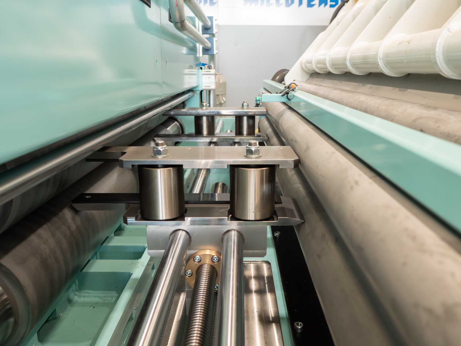
– Overlapping motorized drive rollers located at the entrance, controlled by a hydraulic system enabling their opening and closing.
– Motorized upper and lower straightening rollers housed in a single tilting block.
– Bulk adjustment of the upper straightening rollers is achieved through motorized mechanical jacks, with height display on a touch panel.
– All rollers can be individually disassembled for precise maintenance or replacement.
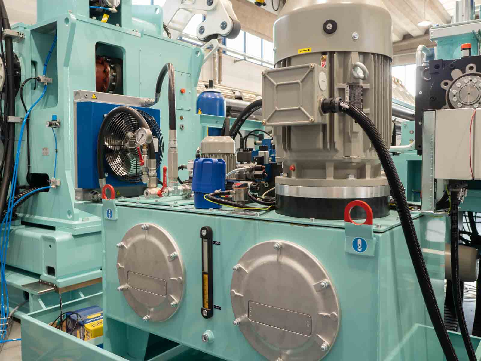
Roller motion is distributed via a gearbox immersed in oil.
Automatic lubrication is provided for universal joints, with a dedicated reservoir for excess oil collection.
Grease-lubricated roller bearings (long life) are employed for both the straightening rollers and counter-rollers.
The tape guide, positioned at the entrance, ensures the tape remains aligned during material advancement.
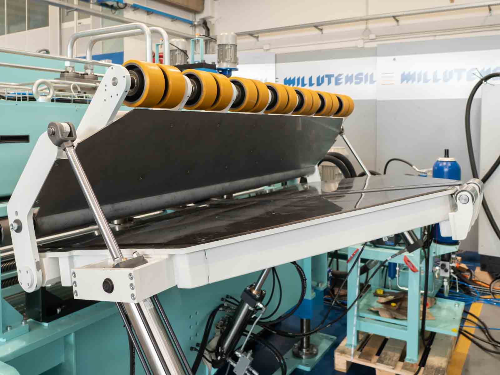
An hydraulic introduction table for the tape aids in its insertion from the coil. The upper deflection roller facilitates containment of material curvature, while the extension of the table facilitates the removal of sheets of different coil diameters.
A wheel encoder, located at the output, verifies the set dimension in the recipe, stopping the system in case of misalignment. The control offers two selectable and memorizable operating modes in the recipe: a) resolver motor, b) metric wheel.
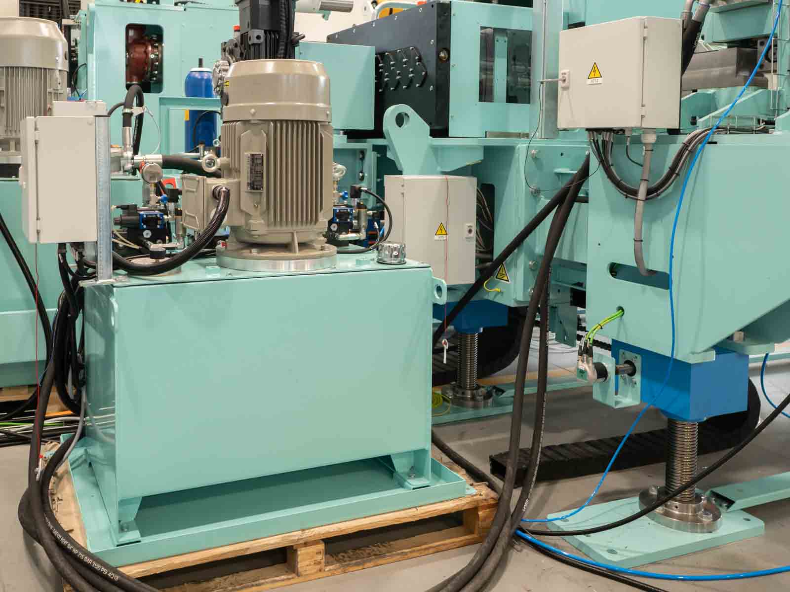
The welded base is equipped with height adjustment through motorized jacks driven by gear motors, with height display (die code) on the control panel.
CYCLING HYDRAULIC SHEAR
The cyclic hydraulic shear is designed to work with strips with a length of 2000mm and a thickness of 3.0mm.
Positioned immediately after the straightening unit, it is properly sized to cut the materials being processed. The cutting blades feature four cutting edges, ensuring effective operation and precision in cuts.
SERVO REEL TECHNOLOGY
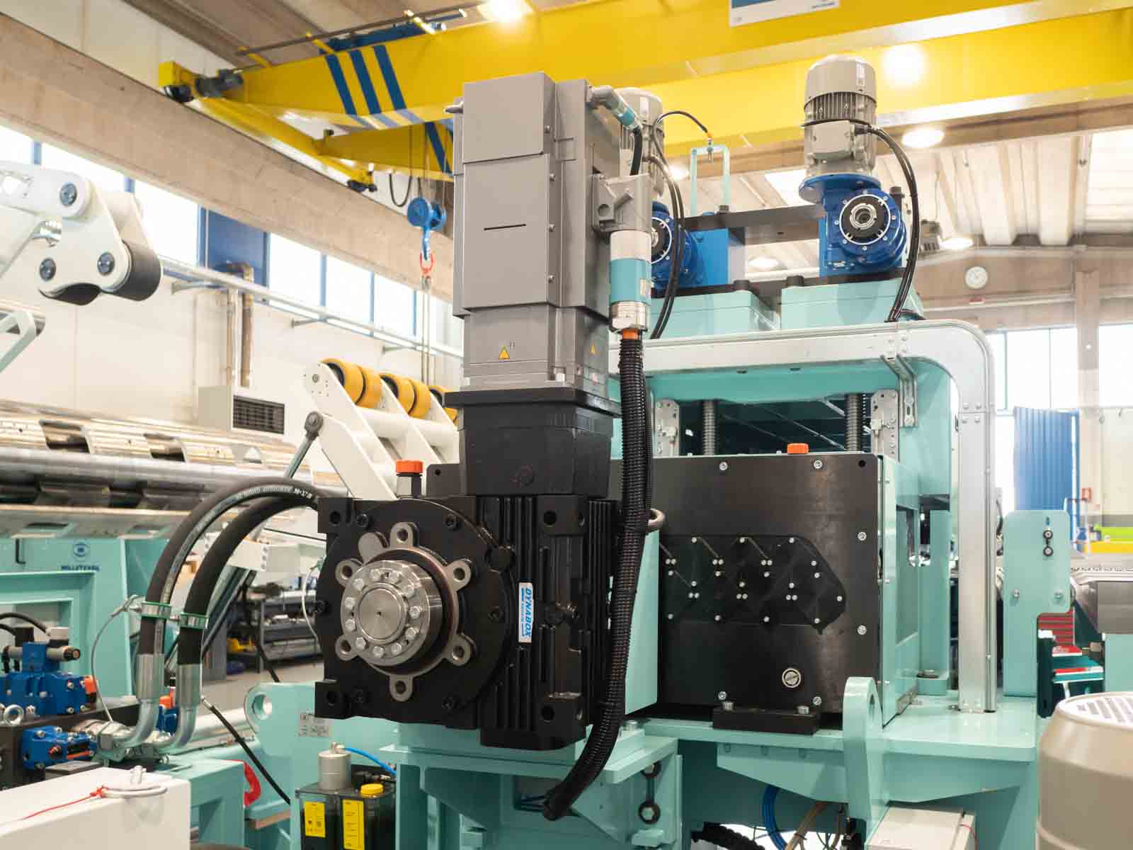
The “Servo Reel” technology, exclusive to Millutensil, is designed to synchronize the unwinding of the coil with the material feed and subsequent processing stages. This system utilizes a servo motor to precisely control the coil unwinding speed, ensuring a constant and uniform material flow during the production process. Thanks to this accurate synchronization, it achieves greater precision and consistency in processing operations, minimizing waste and enhancing overall production efficiency.
HUMAN-MACHINE-INTERFACE
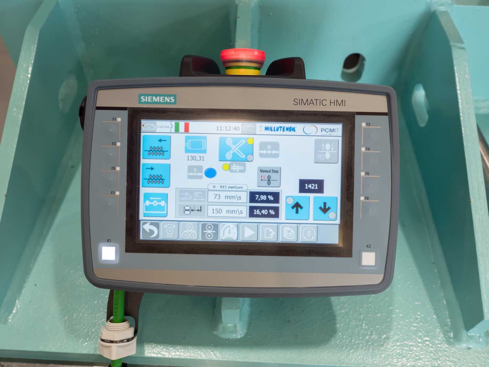
The entire production line is managed by a Siemens mobile touch screen control panel, providing comprehensive control and oversight. This advanced interface ensures seamless operation and facilitates efficient management of the production process.
VIDEO
GALLERY

Office: Corso Buenos Aires, 92 – 20124 Milano – Italy Tel. +39 02 29404390 – Fax +39 02 2046677
Plant: Via delle Industrie, 10 – 26010 Izano (CR) – Italy – info@millutensil.com – millutensil.com
