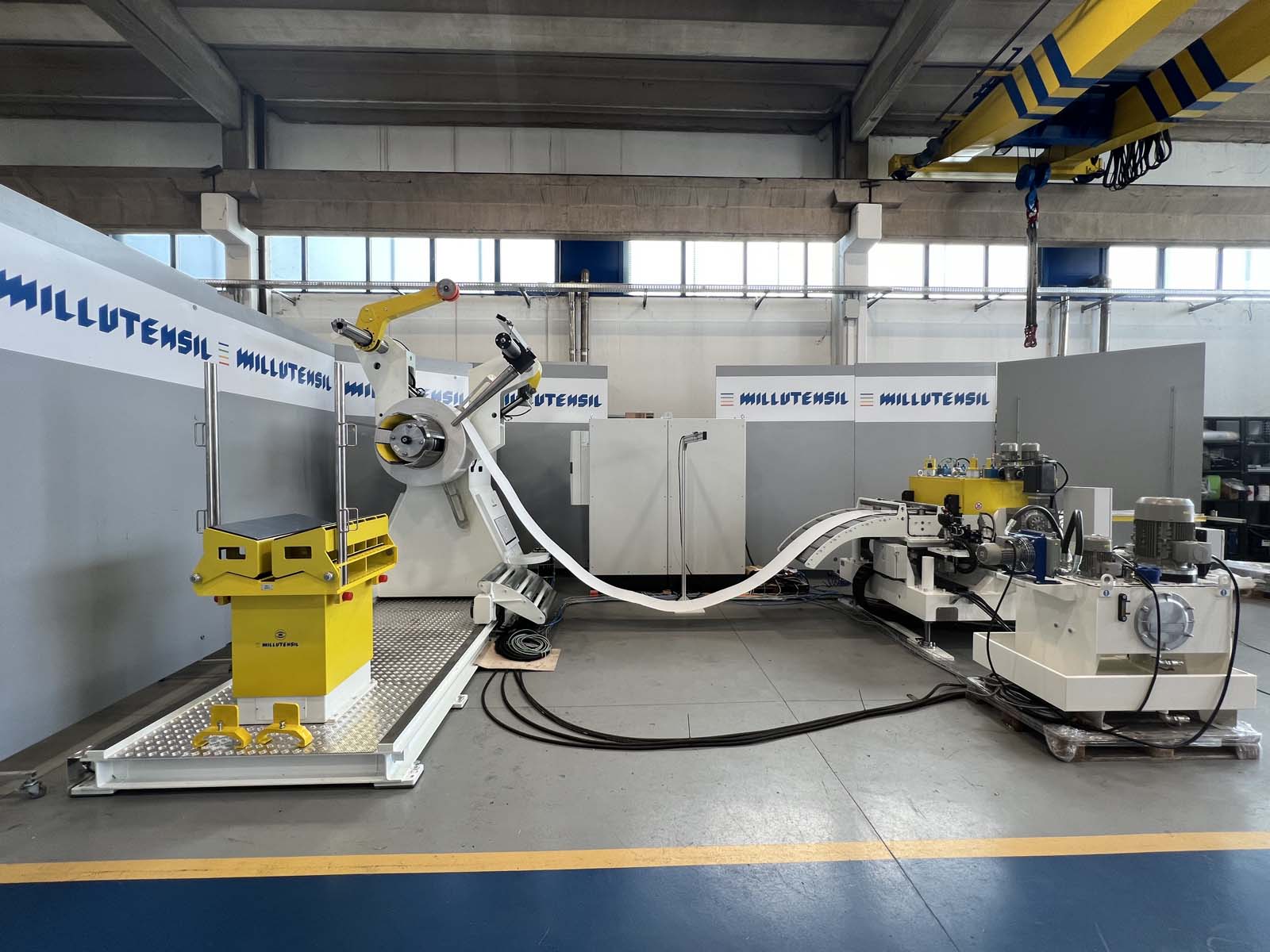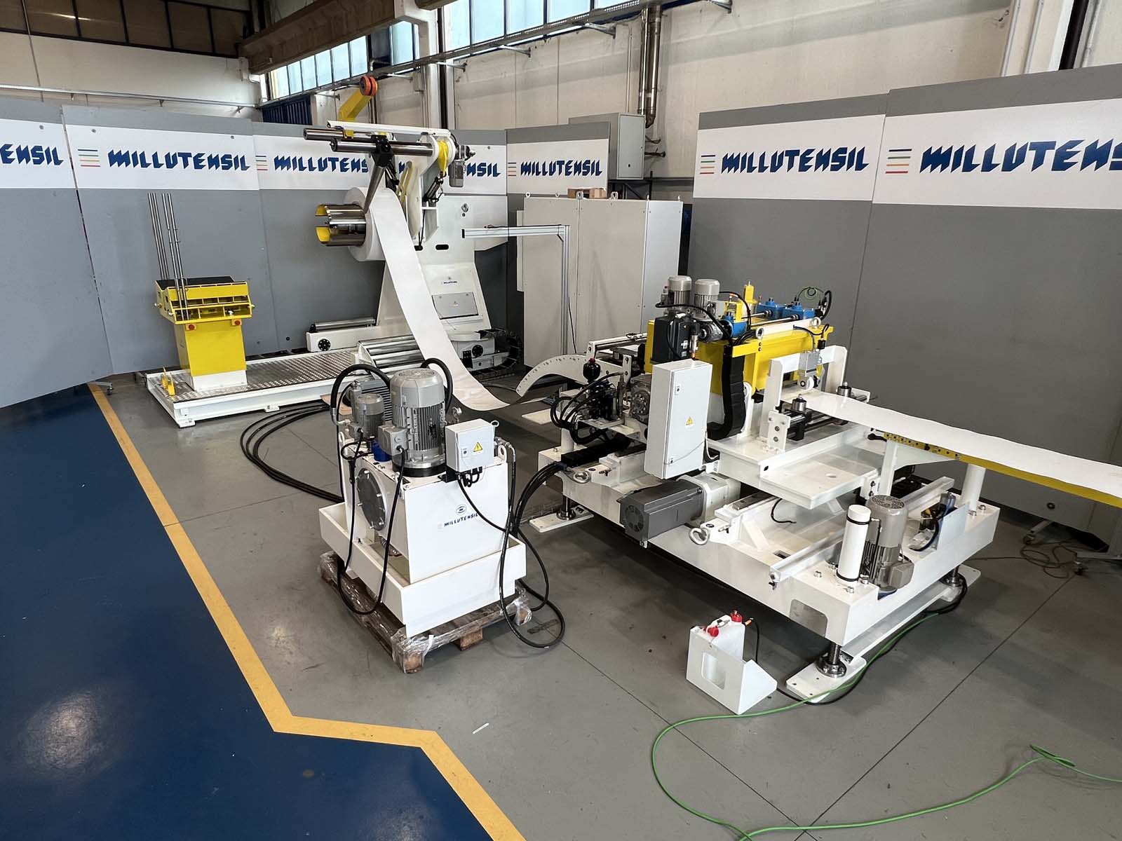

COMPACT ZIG-ZAG STRIP FEEDING LINE FOR 550ton PRESS
According to layout 054.904.03055
| Parameter | Value |
| Decoiler capacity | 8,000 kg |
| Minimum outer diameter of coil | 520 mm |
| Maximum outer diameter of coil | 1,800 mm |
| Minimum width | 80 mm |
| Maximum width | 600 mm |
| Maximum thickness | 3.5 mm |
| Material type | Steel / Alu |
virtual 3D
Press the mouse and move to explore the line from all angles. Use the scroll wheel to zoom in.
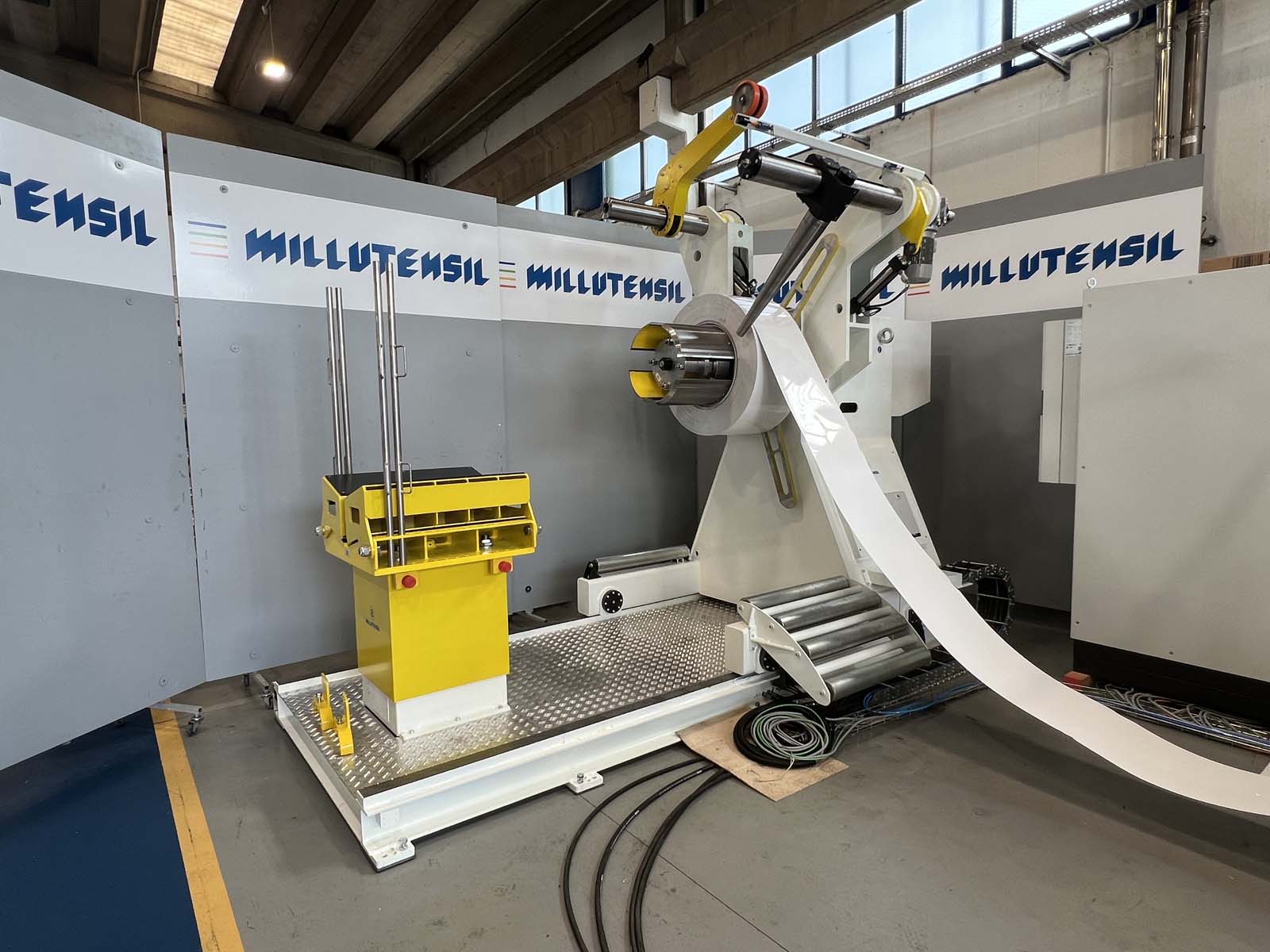
1 Decoiler
Bearing structure made of welded steel, widely dimensioned
-Spindle shaft supported by double roller bearings
-The expansion and contraction of the spindle is carried out by cones with hydraulic movement
1.1 Motorized side translation
By wheels on floor rails for coil loading strip alignment
1.2 Snub Arm
Integrated in the upper part of the decoiler, moved by means of a hydraulic cylinder, it is sized to contain the materials during insertion. The wheels are coated with polyurethane to allow not to damage the surface of the material, the movement is activated by the control panel.
1.3 Conical lateral guide
Integrated into the upper part of the decoiler, oriented at 10 o’clock
The feed-in movement takes place by means of an hydraulic cylinder
The width adjustment is motorized at height
with the possibility of storing the position in the recipe.
The lateral conical guides ensure the coil containment.
1.4 Stationary loading cradle
Fixed supporting structure in electro-welded steel
hydraulic lift duly sized to allow the centring on the spindle, of the coils
with different diameters.
V saddle for coil centring covered in polyurethane to prevent the strip from damages
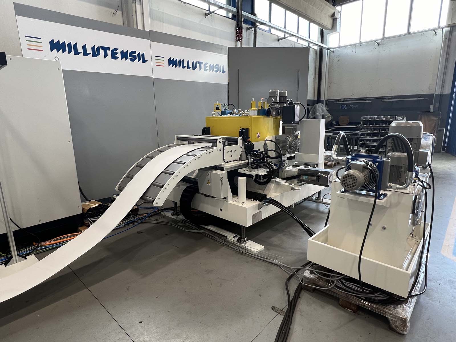
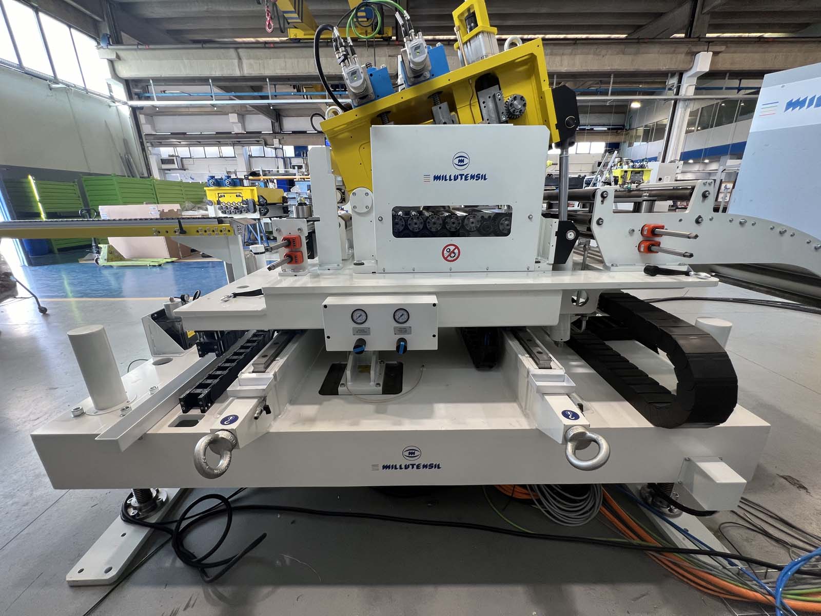
2 Straightener
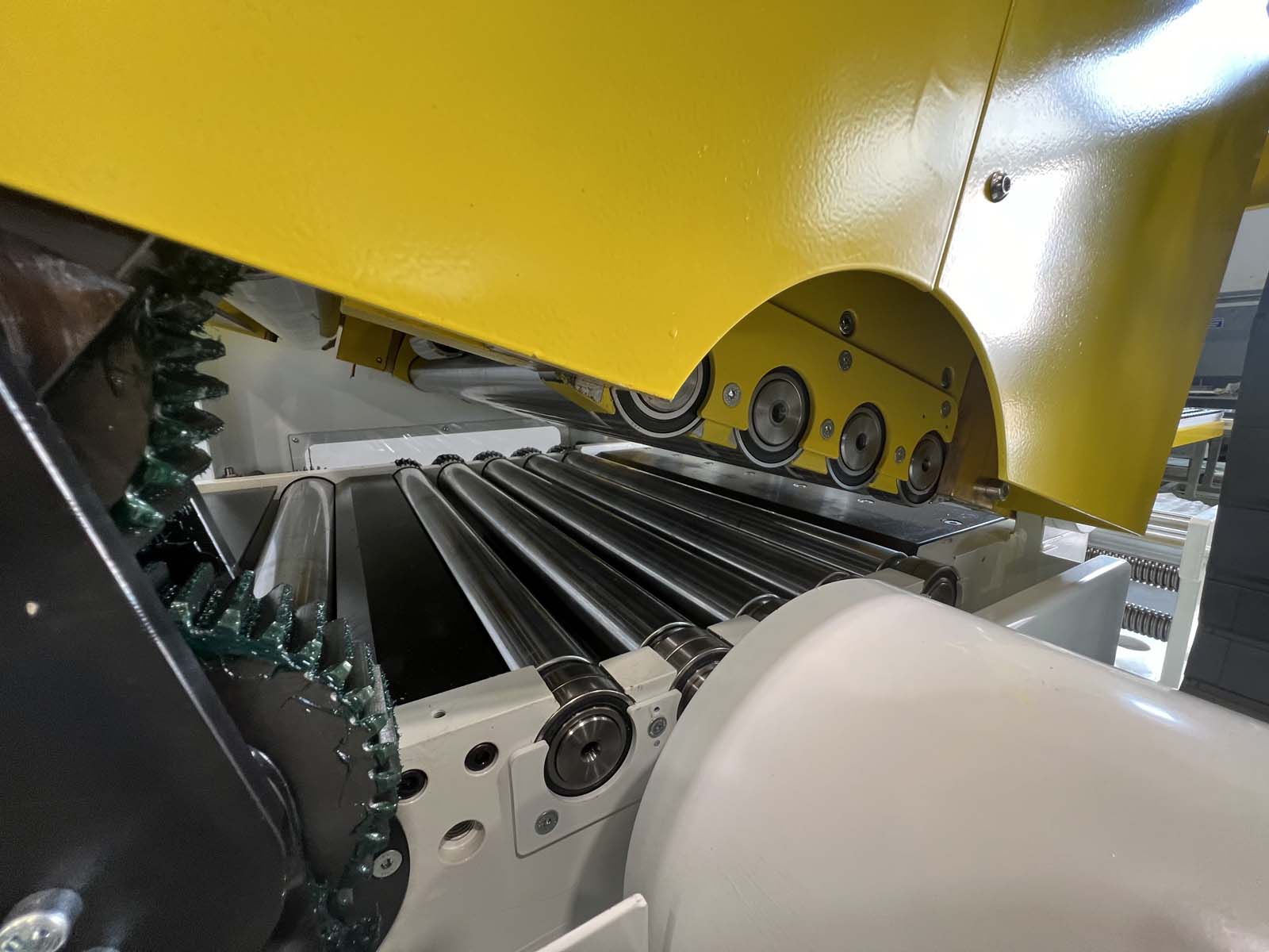
With “book-type” opening head by means of two hydraulic cylinders
For strip beginning insertion
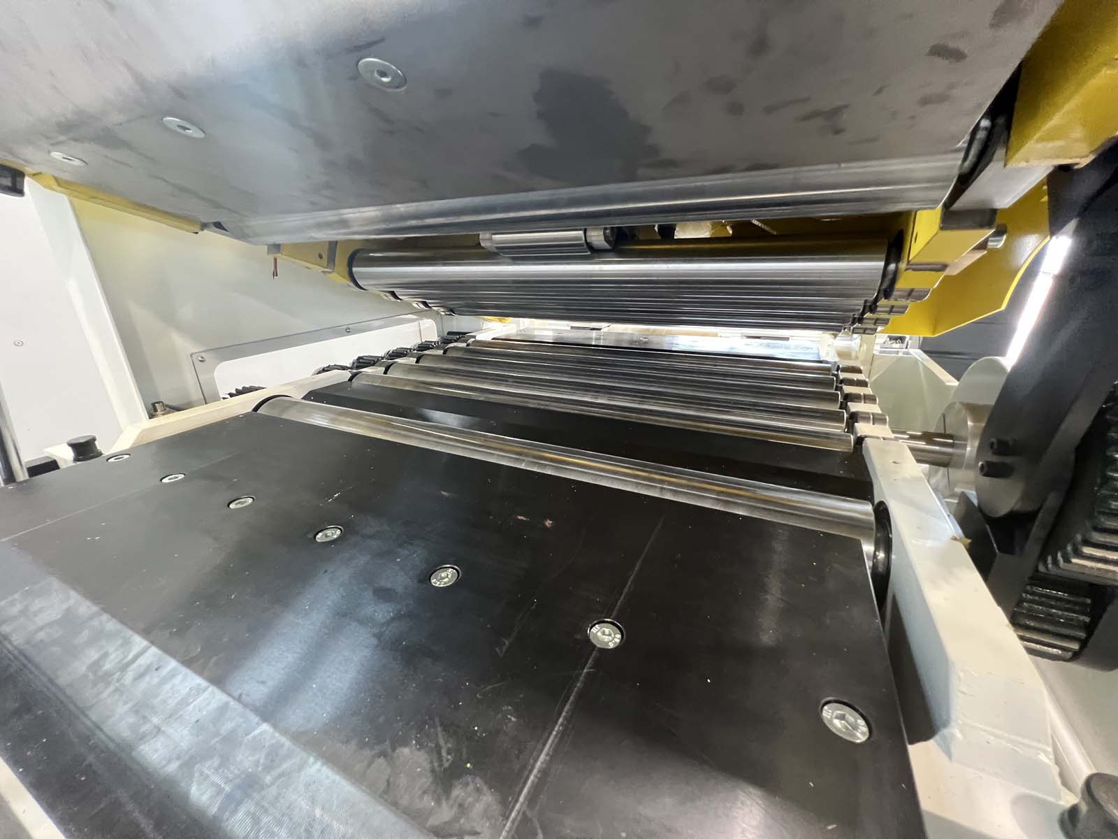
-Motorized overlapping driven pinch rollers placed at the entrance with pneumatic opening and closing of the upper rollers
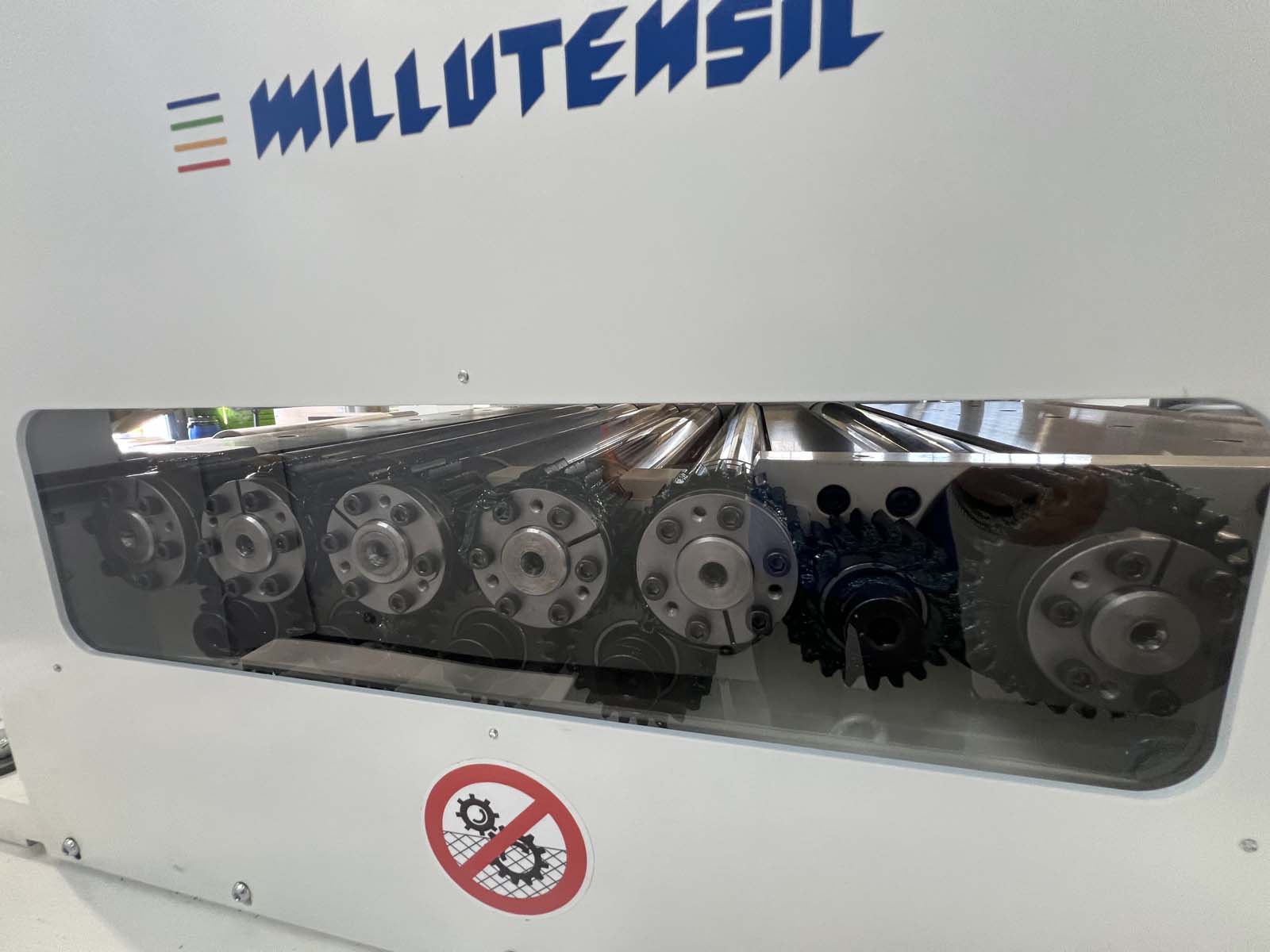
-Motorized lower straightening rollers
-Idle upper straightening rollers contained in a wheighing monobloc
-Block adjustment of the upper straightening rollers by means of motorized mechanical jacks with quota display on the touch panel
-All rollers have the possibility of being dismantled individually for accurate maintenance or for their substitution.
2.1 Lateral translation Zig/Zag axis Y
Lateral translation of the straightening head on recirculating ball bearings
With transmission via endless screw
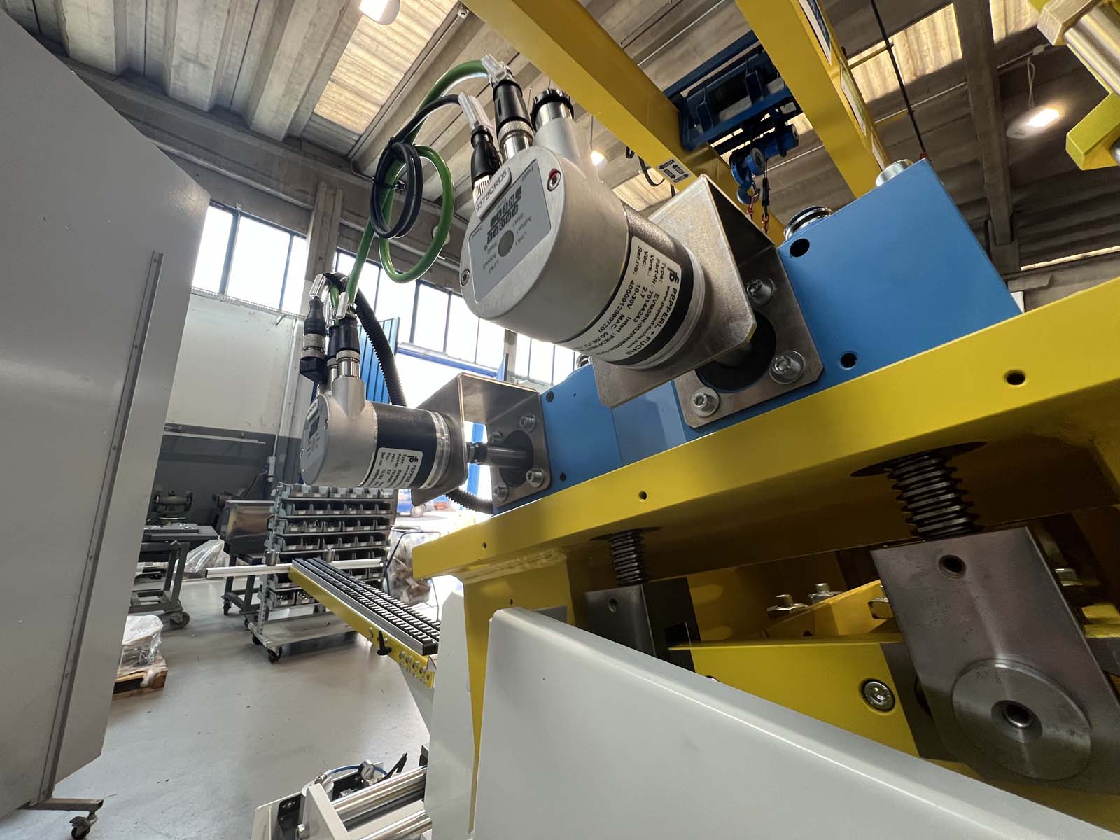
Motorization by Brushless motors
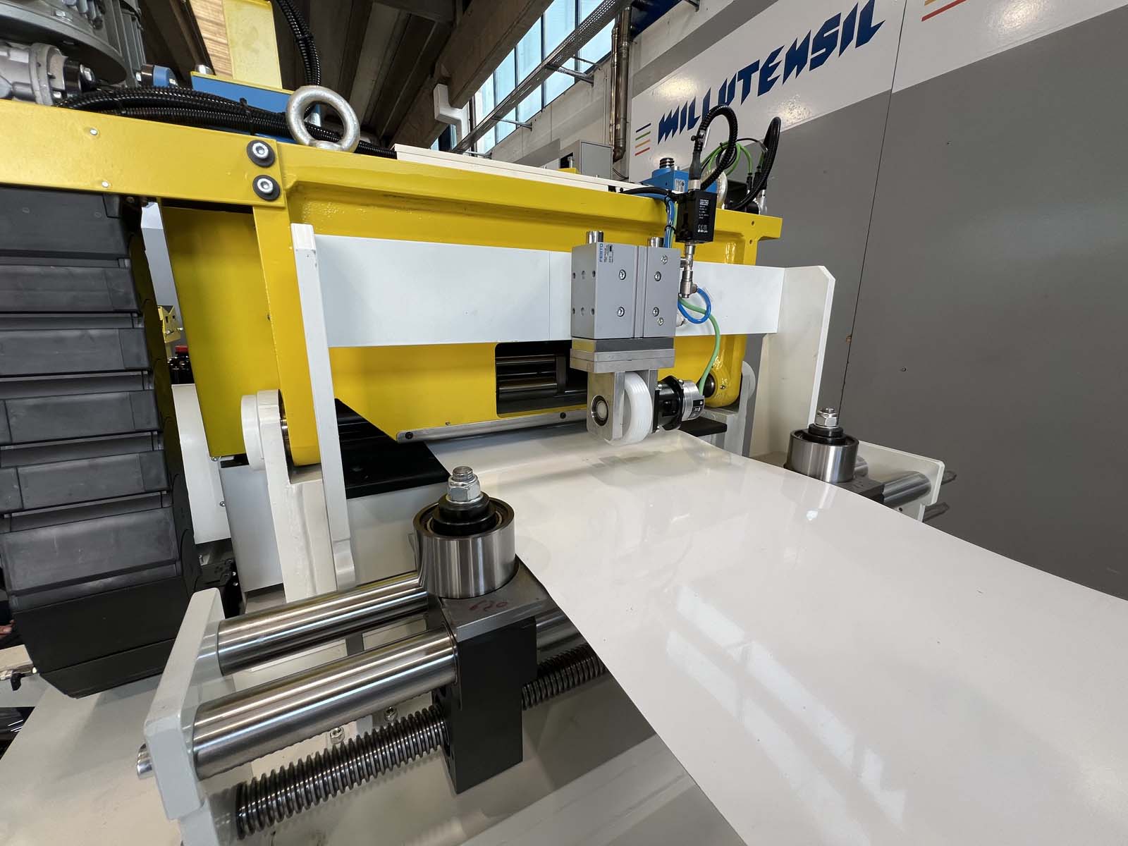
2.2 Strip guide
Positioned at the entry. The rollers allow the strip to be guided during the material feeding
2.3 Material feed-in roller conveyor
2.4 Encoder wheel
Placed at the exit, it checks the quota set in the recipe, stopping the system in case of non-positioning.
The control has two operating modes that can be set at choice and stored in the recipe, A) motor resolver B) metric wheel
2.5 Electro-welded base-frame, height adjustment
By means of mechanical jacks driven
2.6 Loop control
Mass contact under decoiler spindle
VIDEO
GALLERY

Office: Corso Buenos Aires, 92 – 20124 Milano – Italy Tel. +39 02 29404390 – Fax +39 02 2046677
Plant: Via delle Industrie, 10 – 26010 Izano (CR) – Italy – info@millutensil.com – millutensil.com
