
The content of this page is strictly confidential and reserved for PROGRESS-WERK OBERKIRCH and MILLUTENSIL personnel only.
Unmatched Experience and Innovation
Welcome to Millutensil SRL, a company with nearly 70 years of history steeped in innovation and expertise. Since the 1980s, Millutensil has been a pioneer in manufacturing machinery for coil processing in the sheet metal industry. Our machines have gained worldwide recognition for their reliability, precision, durability, and remote assistance capabilities.
At Millutensil, we pride ourselves on our commitment to staying at the forefront of technological advancement. Our relentless pursuit of innovation ensures that we continue to provide our customers with cutting-edge solutions that meet their evolving needs.
Choosing Millutensil means choosing a technological partner that stands by your side every step of the way. Our dedicated team is committed to providing unparalleled support and expertise, ensuring that your operations run smoothly and efficiently.
With Millutensil, you’re making the best possible choice for your business. Experience the difference of working with a company that combines decades of experience with a passion for innovation. Join us in shaping the future of sheet metal processing.
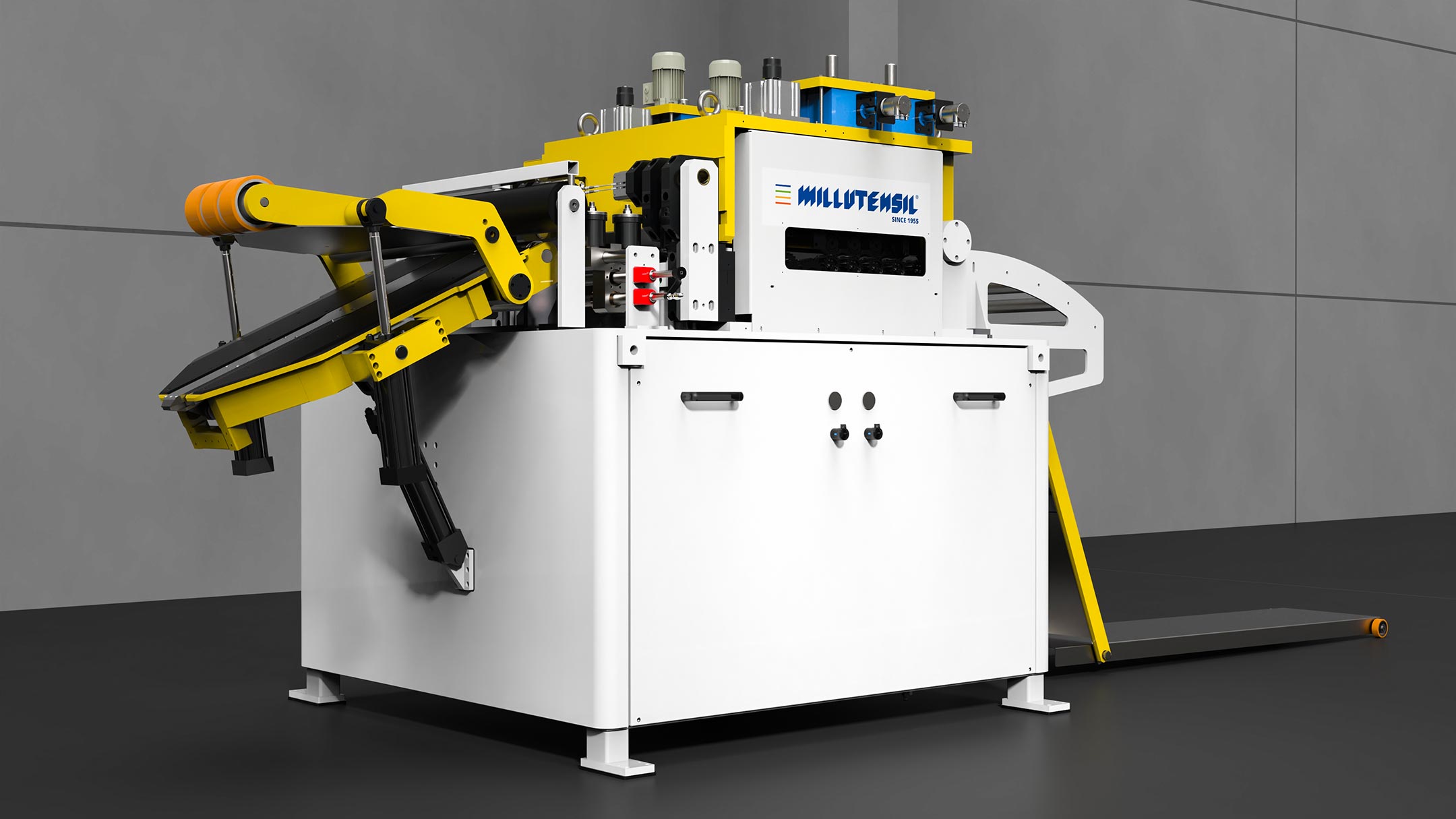
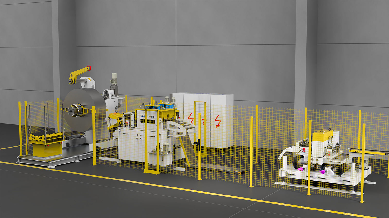
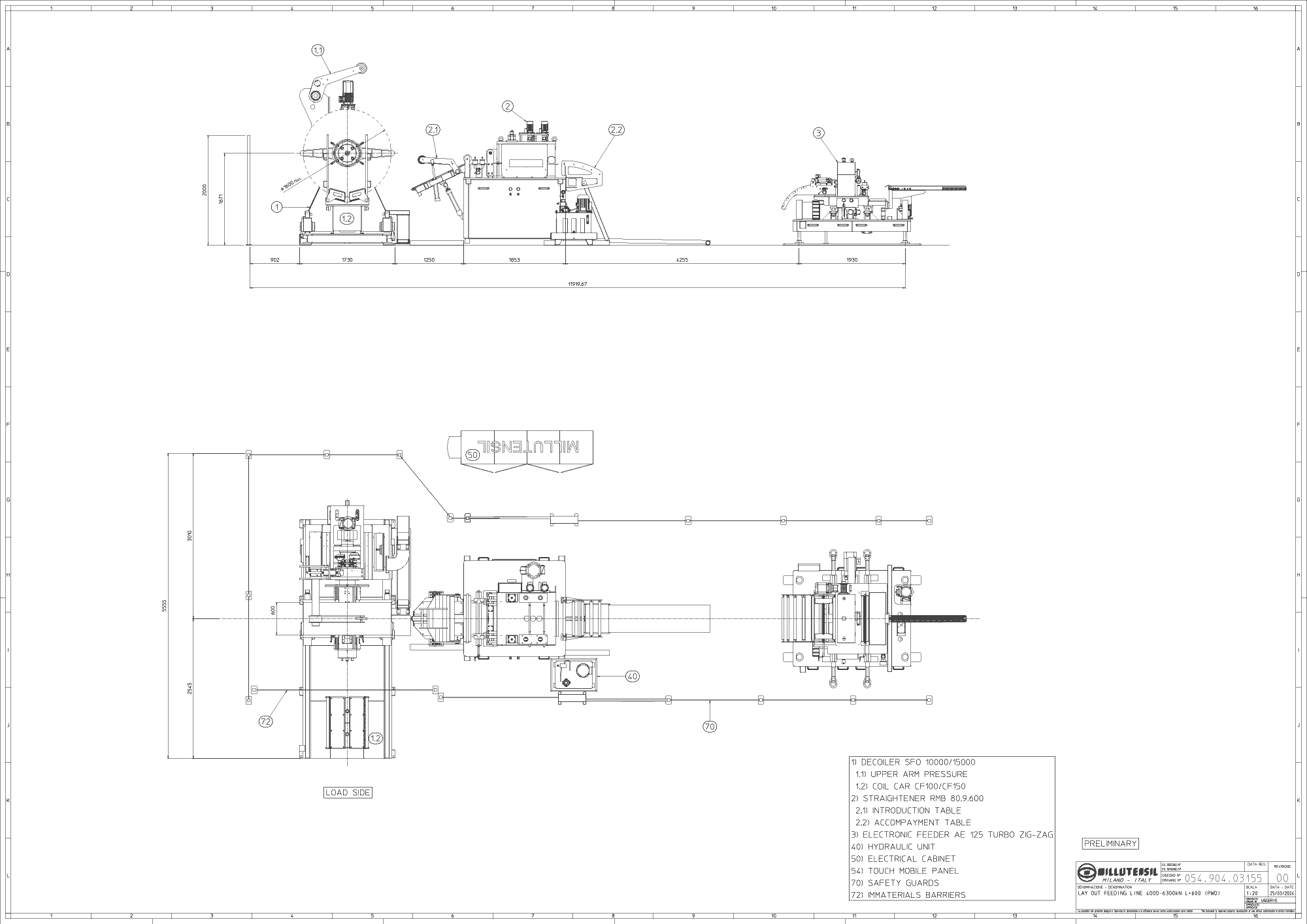
STRIP FEEDING LINE IN LONG CONFIGURATION
According to Layout 054.904.03154
Strip Feeding Line in Long Configuration, designed to efficiently supply material to a 400 ton or 630 ton press.
This comprehensive line consists of a decoiler, straightener, and electronic feeder, meticulously crafted to seamlessly integrate into your production process.
SFOC 10000 + RMB 80.9.600 + AE 125 ZZ | Project 400 Ton “SERBIA”
| Description | Unit | Data |
|---|---|---|
| Decoiler capacity | Kg | 10.000 |
| max. outer diameter coil | mm | 2.000 |
| max. width | mm | 600 |
| min. thickness | mm | 1 |
| max. thickness | mm | 3 |
| Material type [Rm] | N/nm2 | Steel |
| Electrical cabinet | 400V – 3PH ±10% – 50Hz ±1% |
SFOC 15000+RMC 60.11.1000+AE 160 ZZ | Project 630 Ton “SERBIA”
| Description | Unit | Data |
|---|---|---|
| Decoiler capacity | Kg | 15.000 |
| max. outer diameter coil | mm | 2.000 |
| max. width | mm | 600 |
| min. thickness | mm | 0,7 |
| max. thickness | mm | 3 |
| Material type [Rm] | N/nm2 | Steel |
| Electrical cabinet | 400V – 3PH ±10% – 50Hz ±1% |

The decoiler ensures smooth unwinding of coils, while the straightener guarantees precise alignment of the strip, minimizing material wastage and enhancing productivity. Our advanced electronic feeder offers precise control over feed rates, ensuring consistent and accurate material delivery to the press.
Below are the details:
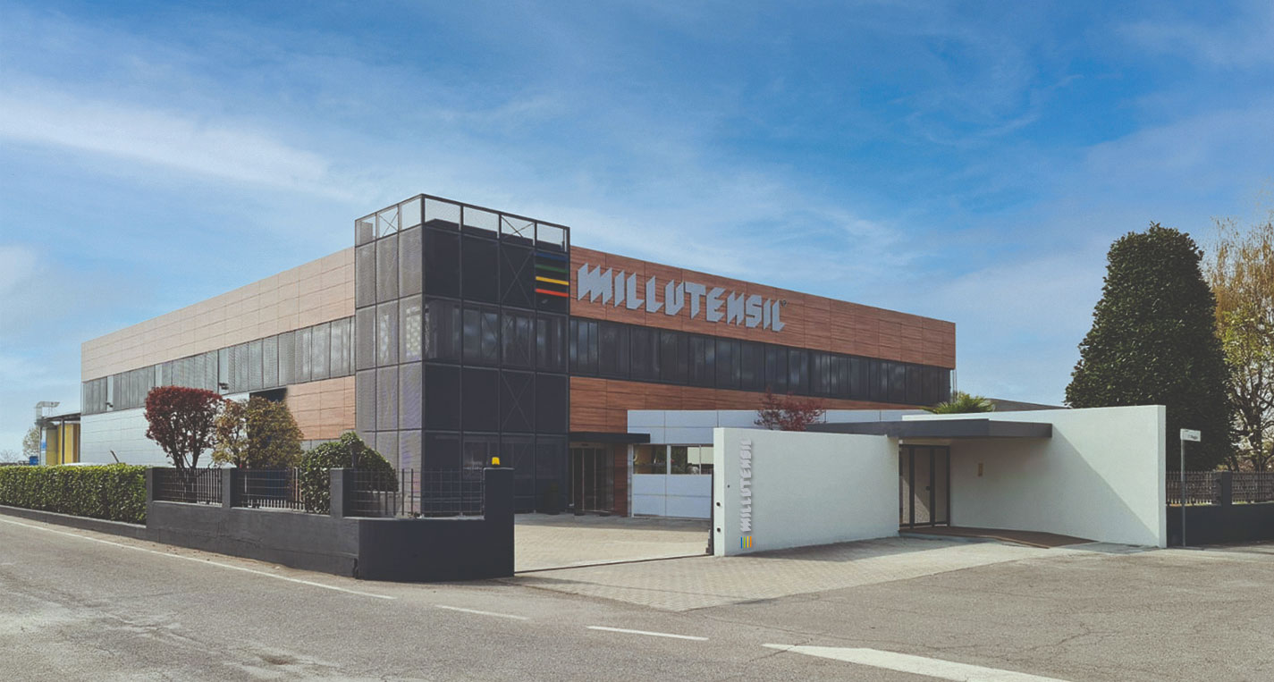
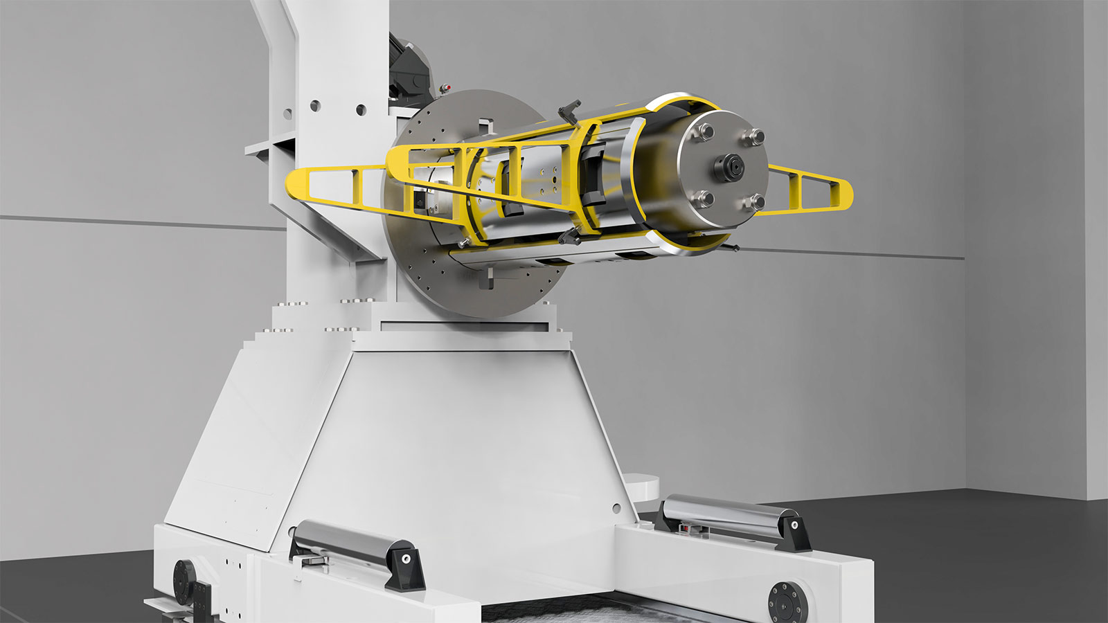
- Decoiler
The decoiler boasts a robust supporting structure crafted from welded steel, ensuring durability and stability in operation. Its generously dimensioned design enhances strength and reliability, capable of withstanding heavy loads with ease.
The spindle shaft is bolstered by double roller bearings, guaranteeing smooth rotation and precise material feeding. For efficient operation, the spindle’s expansion and closing are facilitated by hydraulic movement activated by wedges.
This advanced mechanism enables quick and precise adjustments, optimizing workflow efficiency.
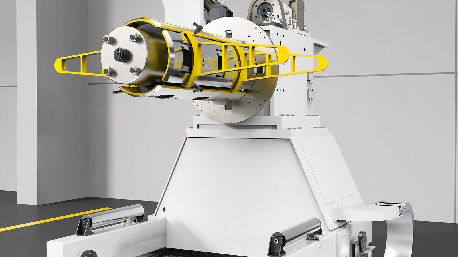
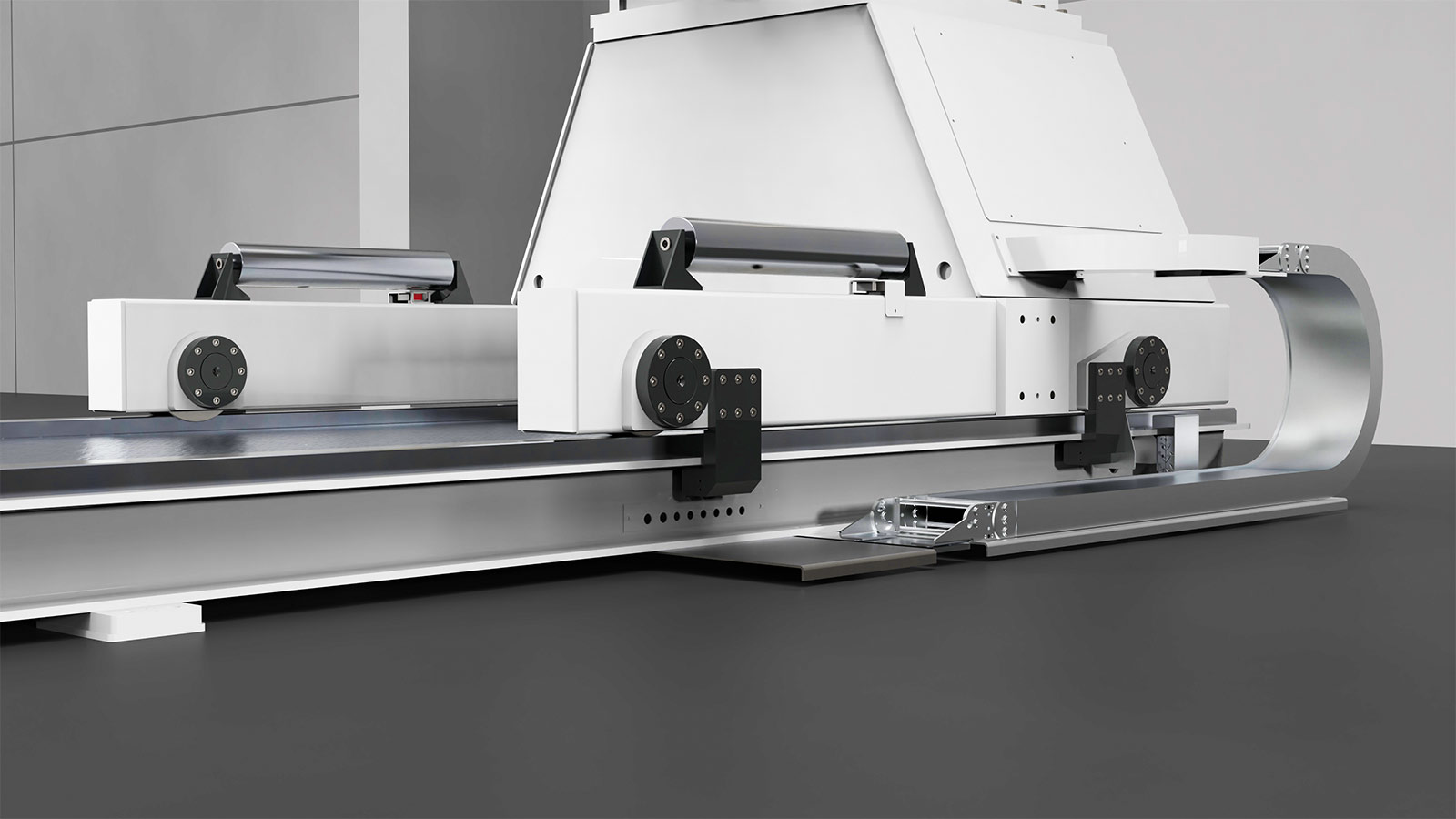
1.1 Motorized lateral translation
By means of wheels on rails on the floor for coil loading belt alignment.
The motorized lateral translation facilitates the movement of coils by employing wheels on rails situated on the based. This mechanism ensures precise alignment of the coil loading belt, enhancing efficiency and accuracy in material handling processes. By automating this lateral translation, operators can effortlessly adjust the position of coils, optimizing workflow and minimizing downtime. Additionally, this feature improves workplace safety by reducing the need for manual handling of heavy materials.
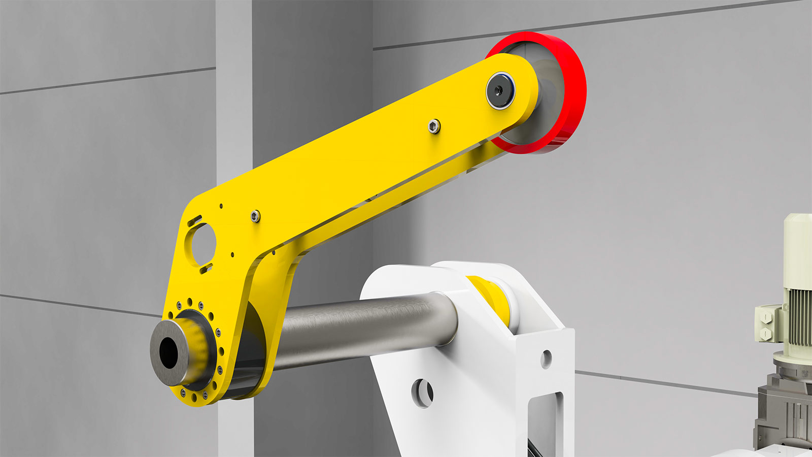
1.2 Pressure arm
Integrated within the upper section of the decoiler, a hydraulic cylinder facilitates its movement, allowing for secure material retention during insertion. Engineered with precise dimensions, this component ensures optimal functionality and stability. Polyurethane-coated wheels further safeguard the material surface from damage, providing smooth and gentle handling. Operators can effortlessly activate the movement from the control desk, simplifying the operation and enhancing workflow efficiency.
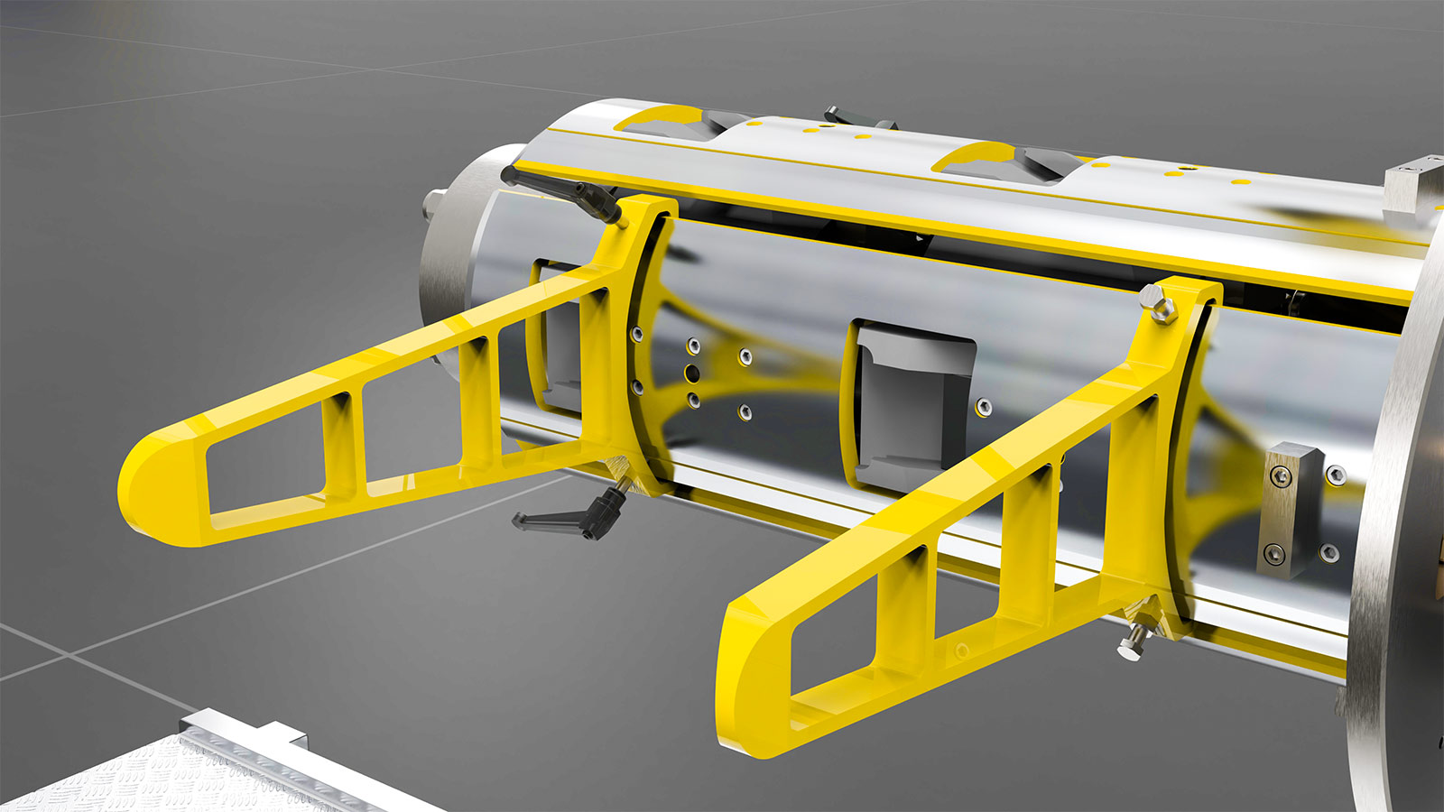
1.3 Coil containment brackets
The coil containment brackets feature a sturdy construction crafted from welded steel, ensuring reliable support and containment of coils during operation.
Designed with ample dimensions, these brackets provide robust reinforcement, capable of securely holding coils of varying sizes and weights.
To accommodate different coil sizes, the brackets are adjustable and can be easily positioned to suit specific requirements.
These features combine to offer unmatched reliability and versatility in coil containment solutions.
1.4 Fixed loading cradle
The fixed supporting structure is meticulously crafted from electro-welded steel, ensuring robustness and stability in coil handling operations.
A hydraulic lifting mechanism, thoughtfully dimensioned, facilitates effortless centering of coils with varying diameters onto the decoiler spindle.
This feature enhances versatility and ease of use, allowing for seamless adaptation to different coil sizes. Moreover, the V-shaped saddle, coated in polyurethane, provides gentle and secure coil centering, safeguarding the integrity of the material surface.
By minimizing the risk of damage to the tape, this design prioritizes material protection and prolongs the lifespan of the equipment.
1.5 Over saddle
The over saddle is specifically designed for efficient coil unloading, with its minimum diameter requirement to be specified according to your needs.
It comprises two hinged blocks securely affixed to the loading cradle. This innovative design ensures stable support and safe unloading of coils, even those with smaller diameters.
The hinged blocks allow for easy adjustment and positioning, accommodating various coil sizes with precision.
With the over saddle in place, you can streamline your unloading process, enhance workplace safety, and optimize workflow efficiency.
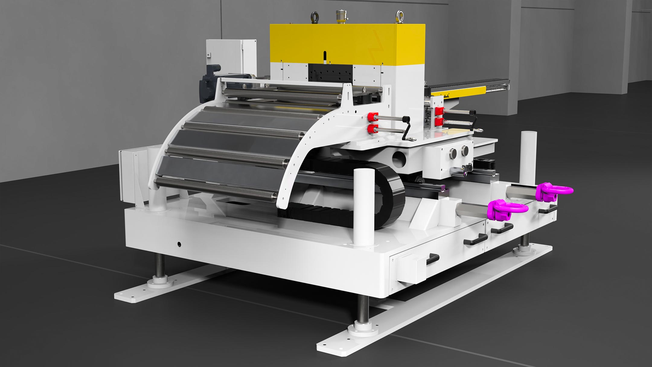
2. Straightener
The straightener plays a pivotal role in transforming coiled metal strips into flat, smooth sheets ready for further processing. Its primary function is to eliminate any residual coil set or curvature present in the material, thus enhancing its flatness and uniformity.
The electro-welded base frame features a fixed height design, providing sturdy support and stability. Crafted through an electro-welding process, this frame ensures structural integrity and durability, capable of withstanding heavy loads and rigorous operating conditions. The fixed height configuration offers simplicity and reliability, eliminating the need for frequent adjustments and minimizing downtime.
Equipped with motorized upper and lower straightening rollers, our straightener offers unparalleled control over the straightening process. This enables operators to achieve precise alignment of the material, meeting stringent quality standards and specifications.
Furthermore, our straightener is engineered with advanced features such as block adjustment via motorized mechanical jacks and disassembly capabilities for individual rollers, ensuring ease of use, maintenance, and customization.
Additionally, the head can be opened like a book, allowing for easy inspection, cleaning, and maintenance of the rollers, which can be individually disassembled for thorough maintenance or replacement.
The loop control system comprises a specifically sized structure positioned across the loop. Integrated into this structure are essential controls designed to effectively manage the material buffer located between the straightener and the laser. This configuration enables seamless coordination, ensuring smooth material flow and preventing disruptions in production. By facilitating continuous monitoring and adjustment of material accumulation, the machine positioned upstream of the line can maintain uninterrupted operation, aligning with the pace of production downstream.
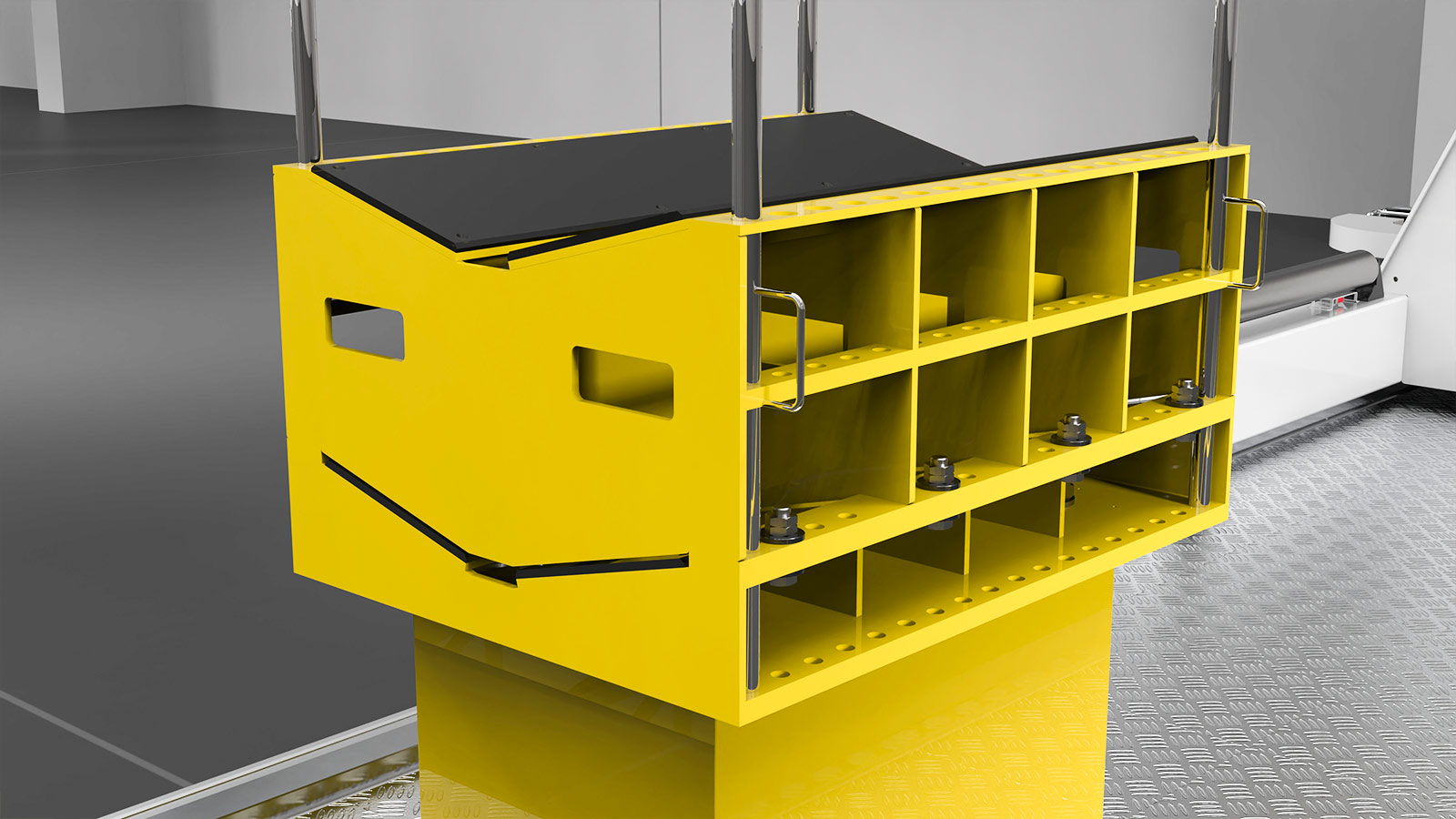
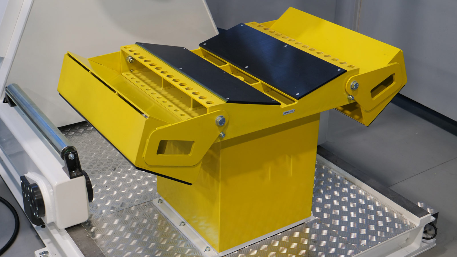
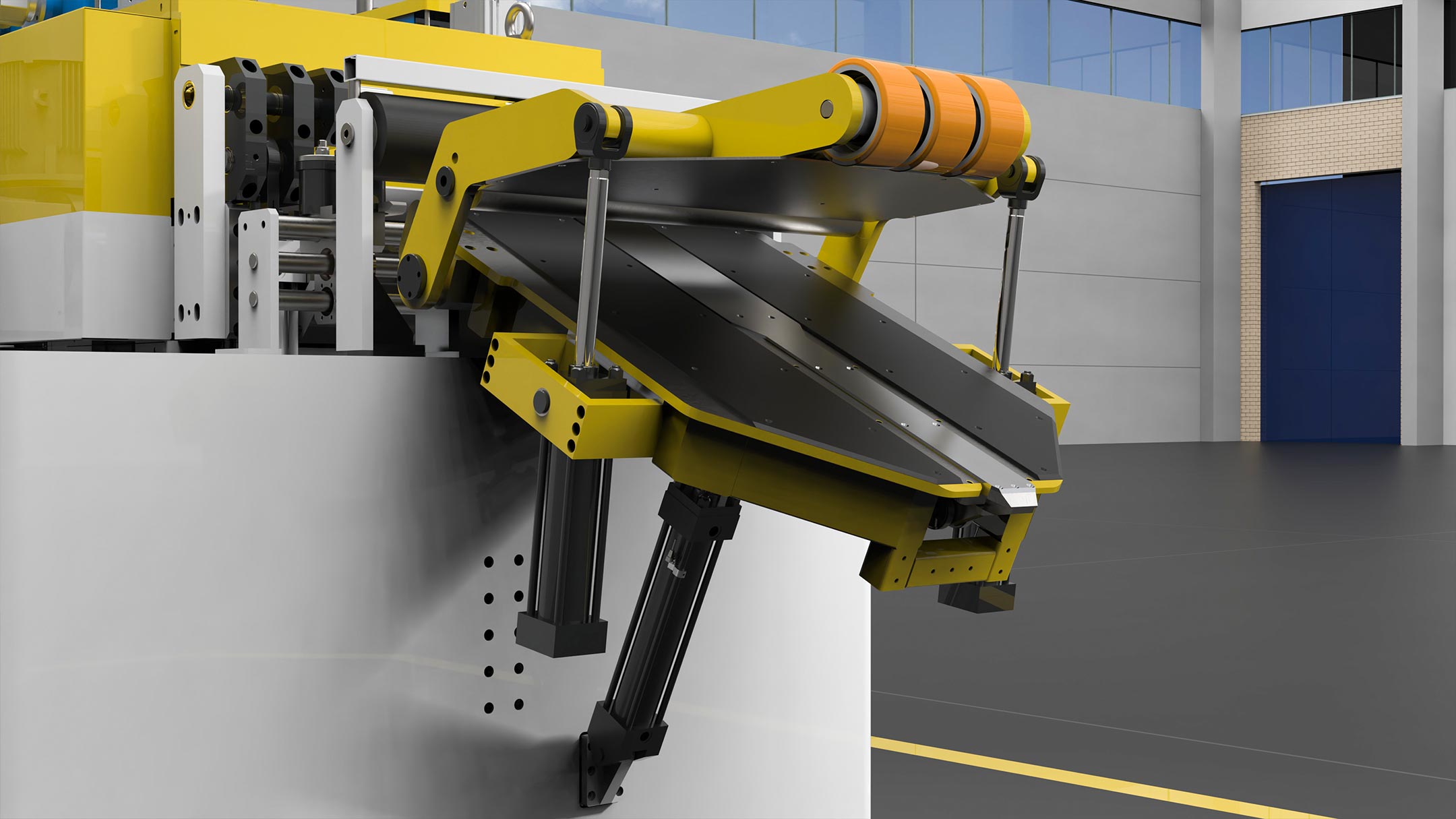
2.1 Introduction table at the beginning of the strip to help insert the strip coming from the coil.
The Introduction table serves as a crucial aid at the outset of the strip insertion process, particularly beneficial for managing material flow from the coil. Its design includes an upper deflector roller, strategically positioned to effectively contain any curvature present in the material. This feature ensures smooth and controlled movement of the strip, minimizing the risk of misalignment or damage. Additionally, the table extension further enhances functionality by facilitating the pickup of sheets from coils of varying diameters.
2.2 Strip guide
The strip guide, positioned at the infeed, ensures precise alignment and control during material feed. Its rollers effectively guide the strip, maintaining stability and accuracy throughout the process.
Operators can manually adjust the guide’s positioning via endless screw adjustment, allowing for fine-tuning according to specific requirements.
The width adjustment is conveniently indicated numerically on the dedicated indicator, providing clear guidance for optimal setup.
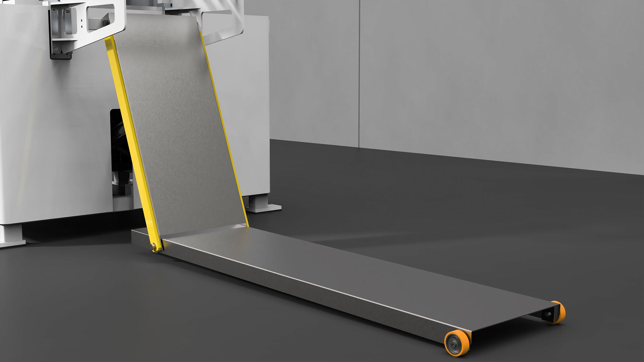
2.3 Accompanying table
The accompanying table serves as a pivotal component within the loop creation area, strategically positioned between the straightener and the laser.
Its hydraulic lift capability allows for seamless adjustment in height, ensuring alignment with the pass line.
This feature enables the creation of a connecting bridge, facilitating the smooth transition of the strip between the two machines.
By eliminating the need for manual handling, it streamlines workflow processes, reduces labor requirements, and minimizes the risk of material damage or misalignment.
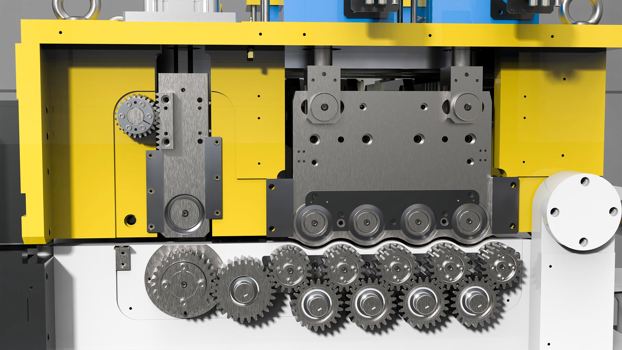
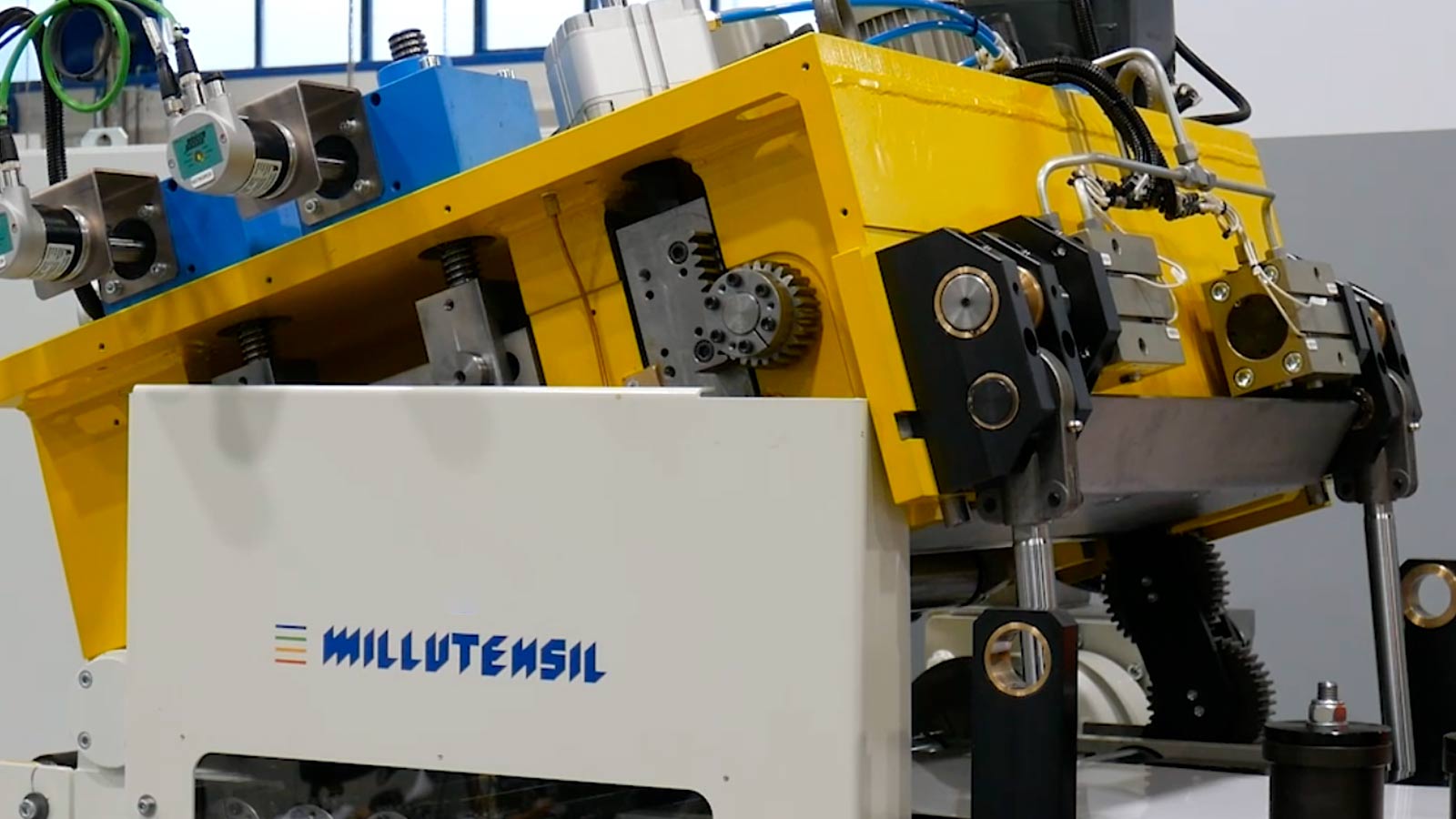
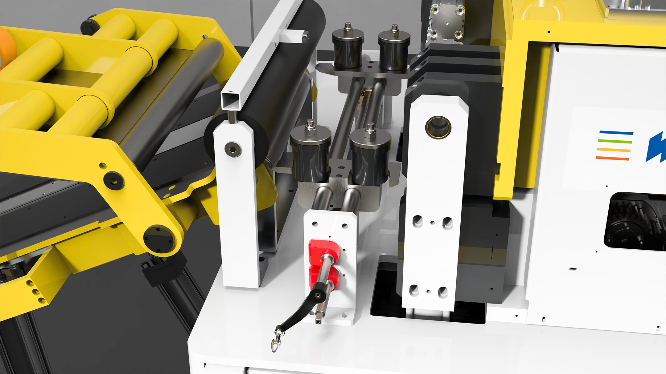
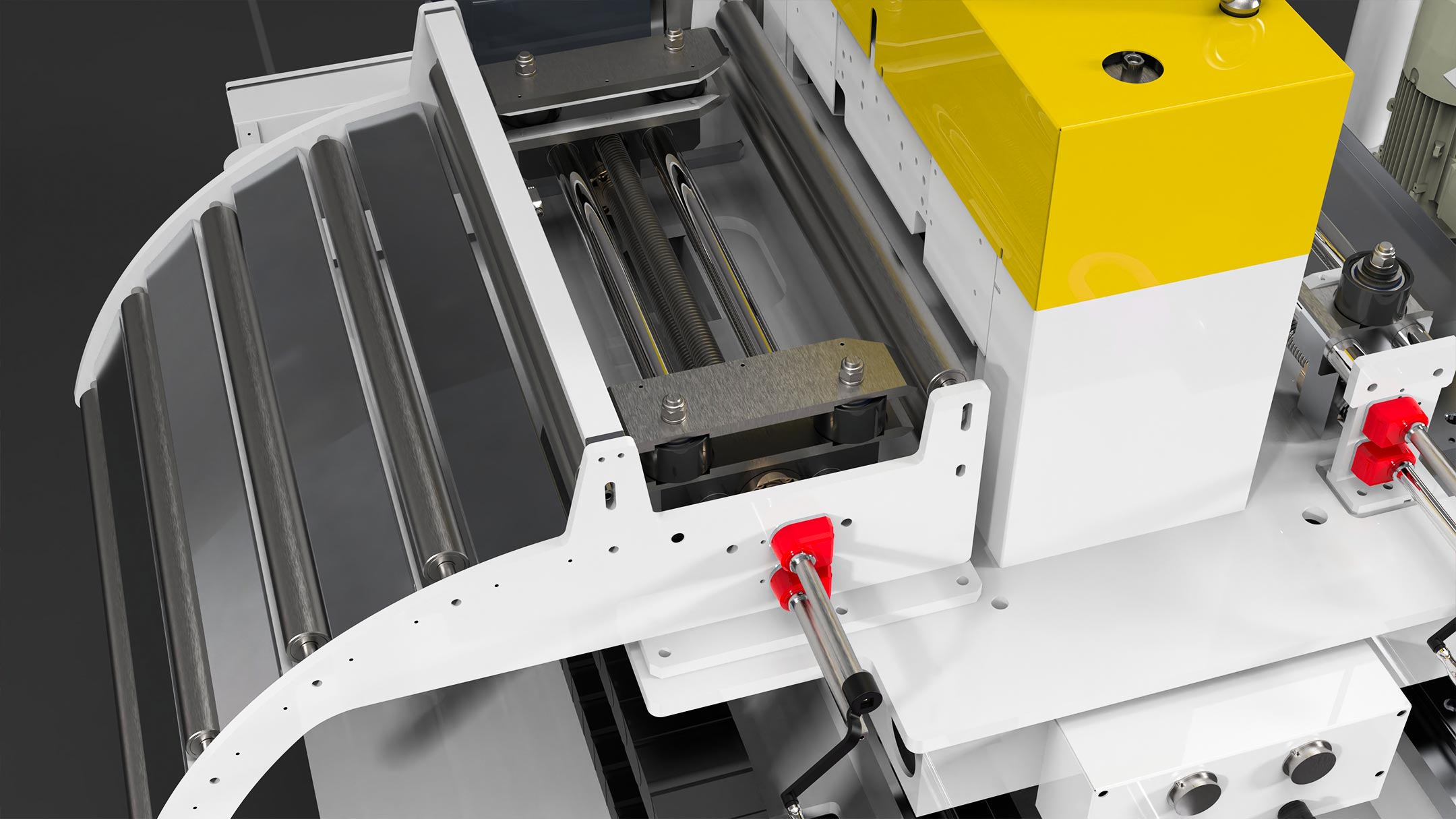
3. Electronic Feeder
The Electronic feeder is the last component in the line before the press. Material coming from the straightener is perfectly prepared for processing under the press.
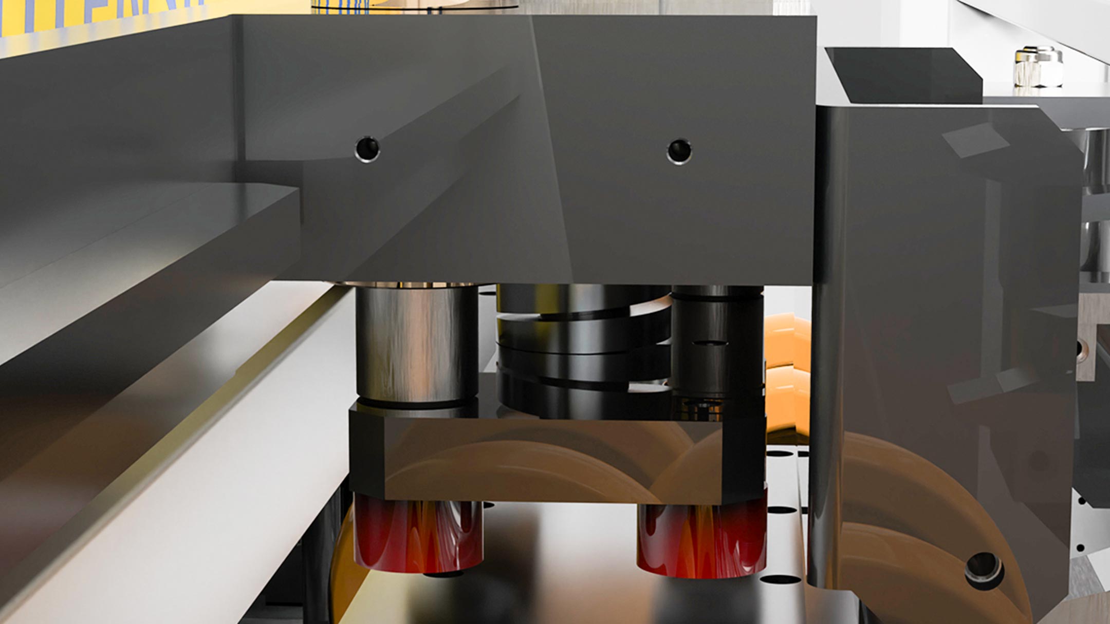
The electrowelded structure, housing the superimposed rollers, forms the backbone of our sheet metal processing system. This structure ensures stability and durability, crucial for handling the demands of industrial operations.
A key feature is the upper roller’s opening mechanism, driven by two synchronized cylinders coordinated through a torsion bar. This setup allows for precise control over the roller’s movements, ensuring smooth operation and optimal material handling.
Operators benefit from manual stroke pressure adjustment and micrometric adjustment of the roller stroke, empowering them to tailor the process to suit the specific requirements of each job. This flexibility is particularly valuable when working with thin or delicate materials, as it helps prevent damage and ensures consistent results.
The upper feeder roller is designed to open, facilitating belt stretching to center the die pilots during punching operations. This feature enhances accuracy and efficiency in the manufacturing process.
Additionally, an infeed roller conveyor equipped with a strip presence sensor ensures continuous material flow and prevents disruptions in production.
The feeder can move laterally along rails driven by Brushless motors. This solution, known as Zig Zag, is particularly suitable for disc cutting operations, enabling the feeding of the press by shifting the sheet metal. This optimizes material consumption and significantly reduces waste.
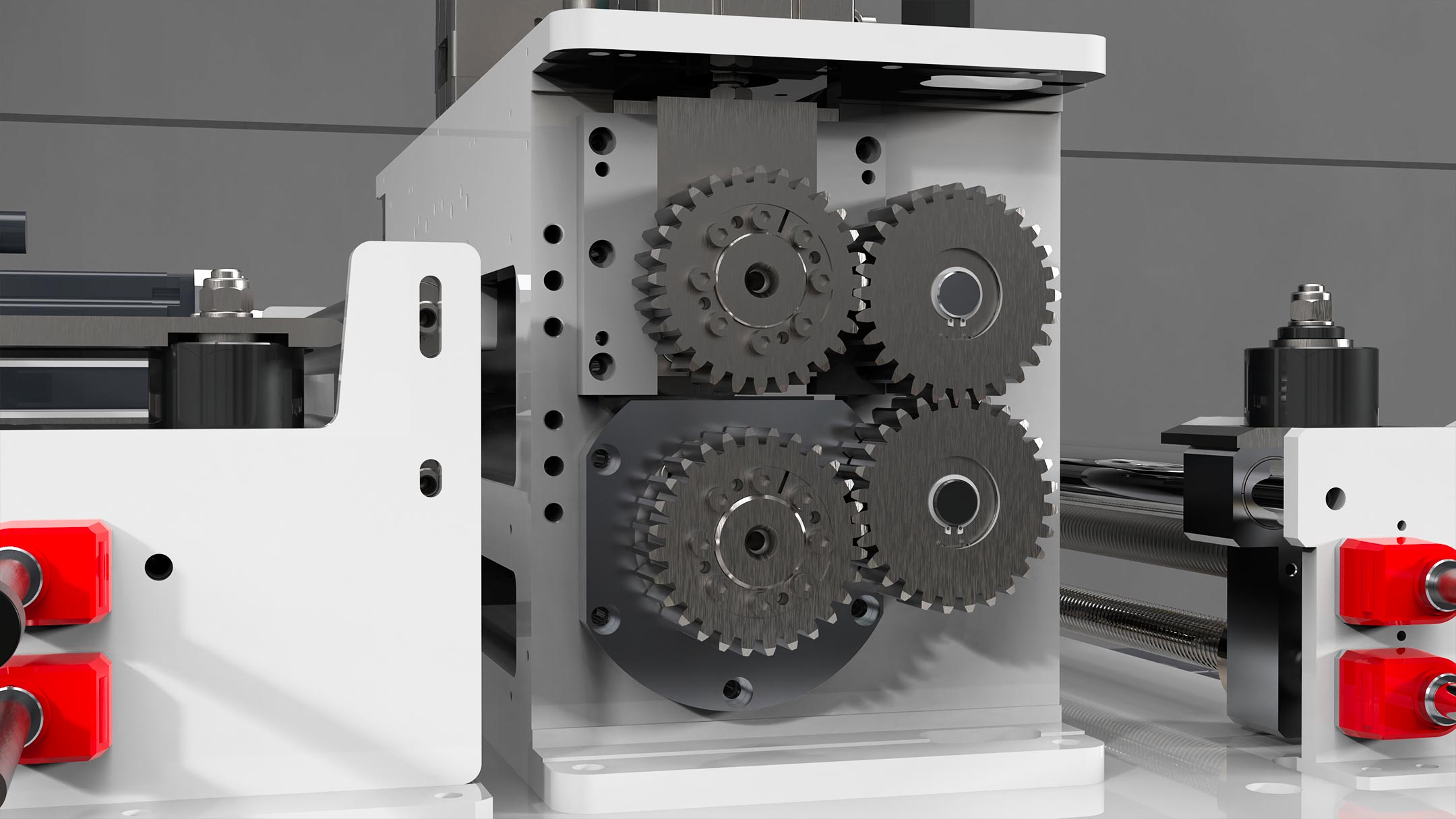
Driving this system is a brushless motor, directly connected to a precision gear motor, ensuring smooth and reliable operation without backlash. This setup guarantees consistent performance and minimizes downtime.
To protect the materials being processed, the rollers are coated with suitable treatments, preventing damage and maintaining product integrity. Furthermore, their design allows for individual disassembly, facilitating careful maintenance or replacement when necessary.
3.1 Lateral/side translation Axis Y
The servo motorized lateral translation, supported by recirculating ball bearings, enables precise movement in Zig-Zag mode and ensures accurate strip centering along the line axis. This advanced system enhances efficiency and flexibility in material handling processes, allowing seamless transitions between operations.
By leveraging servo motor technology and precision bearings, it facilitates optimal alignment of the strip, minimizing deviations and maximizing productivity. Whether in Zig-Zag mode or during strip centering, this innovative solution ensures consistent performance and streamlined operations, empowering manufacturers to achieve superior results in sheet metal processing applications.
3.2 Strip guide
The strip guide, positioned at the infeed, ensures precise alignment and control during material feed. Its rollers effectively guide the strip, maintaining stability and accuracy throughout the process.
As in the straightener, the operators can manually adjust the guide’s positioning via endless screw adjustment, allowing for fine-tuning according to specific requirements.
The width adjustment is conveniently indicated numerically on the dedicated indicator, providing clear guidance for optimal setup.
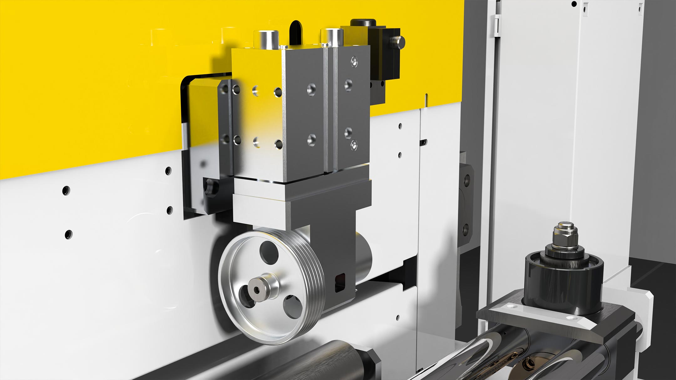
3.3 Strip blockage clamp
The strip blockage clamp features a pneumatic system with a negative instantaneous operation, utilizing springs. Positioned strategically before the feed rollers, this mechanism swiftly blocks the strip during sudden line emergencies, preventing it from falling back.
This proactive approach enhances safety and minimizes potential damage or disruptions to the production process.
By swiftly responding to emergencies, the clamp ensures continuous workflow and prevents costly downtime.
3.4 Wheel encoder
The Wheel encoder, situated at the outlet, serves to verify the preset quota outlined in the recipe. Should the quota not align with the set parameters, the system halts operation, ensuring precision and accuracy in production.
This control mechanism offers two customizable operating modes, both of which can be tailored and stored within the recipe for future use. Mode A utilizes a motor resolver, while Mode B employs a metric wheel.
This versatility allows for seamless adaptation to varying production needs, providing operators with enhanced flexibility and control over the manufacturing process.
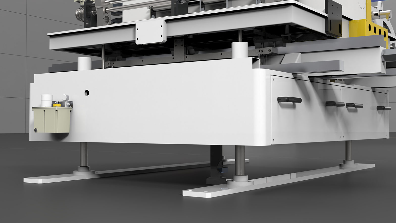
3.5 Base frame with working height adjustment
The base frame features a versatile working height adjustment system.
This functionality is achieved through screw jacks controlled by gearmotors, ensuring precise and effortless adjustment.
Operators can easily control the height settings using the gearmotors, with the amount displayed conveniently on the Touch Panel interface.
This allows for quick and accurate adjustments to accommodate different production requirements or ergonomic considerations.
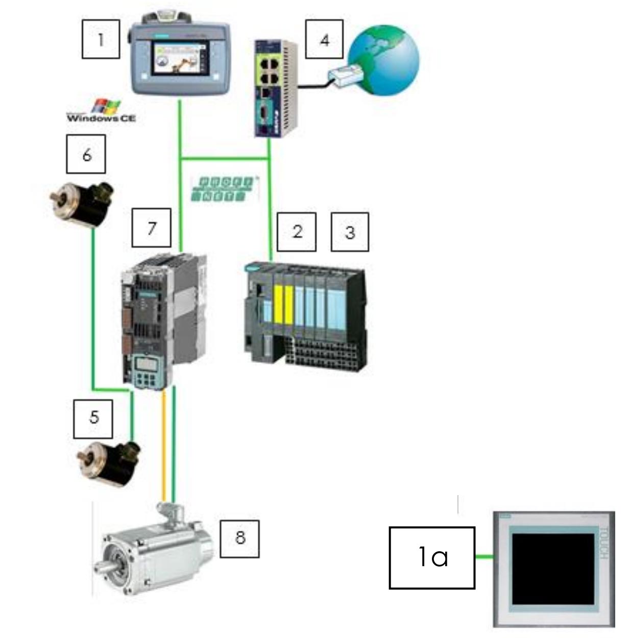
4. Automation system TAS1
TAS1 Automation System, a cutting-edge solution designed to revolutionize industrial automation. TAS1 seamlessly integrates advanced technologies to streamline production processes, enhance efficiency, and ensure precision in manufacturing operations. With its sophisticated components and intuitive interface, TAS1 empowers operators to optimize workflow management, monitor equipment performance in real-time, and swiftly respond to production challenges. From HMI interfaces and PLC controllers to online teleservice capabilities, TAS1 sets a new standard for automation excellence, offering unparalleled reliability, flexibility, and scalability.
The automation system essentially consists of:
- HMI with mobile panel KTP700F Siemens touchscreen 7” in color – L = 10 M (optional) Integrated with TIAP programming software 1A. Fixed color touch panel TP 1200 Siemens 12”
- PLC Siemens IM151F by Command Logic
- PLC-integrated safety management
- Online teleservice with EWON card
- EU standard wheel encoder for actual sheet metal displacement reading
- CAM positioner for electronic CAM function (optional)
- Servo-drive Siemens
- Brushless servo motor with integrated Siemens resolver
4.1 Standard interface with the press
The interface with the press, encompassing both functional and safety aspects, is facilitated through PN-ProfiSafe. Our supplied PN-PN coupler will be seamlessly integrated into our switchboard.
The only contact signals required are the following:
- Feeder start cam
- Pilots cam (if any)
- Auxiliary cam (if any)
4.2 Software characteristics
► Management of ‘recipe’-type operator programs directly on the mobile panel for setting all
operating parameters (acceleration, deceleration, speed, pace, repetitions, cycle, etc.).
It is possible to manage 500 recipes with 20 different steps per recipe and one hundred
repetitions each.
► Comprehensive fault diagnostics via visualized and muted alarms
► Individual step length settable in metric (0 ÷ 9,999.99 mm)
► Display of the amount reached
► Single or continuous automatic cycle operation
► Manual jog+/jog- and test single step movements at preset reduced speed with quota
storage
► Counting decreasing pieces
► Start/stop auto cycle from panel
► Sheet metal displacement control with resolver as an option actual sheet metal
displacement measurement via wheel encoder
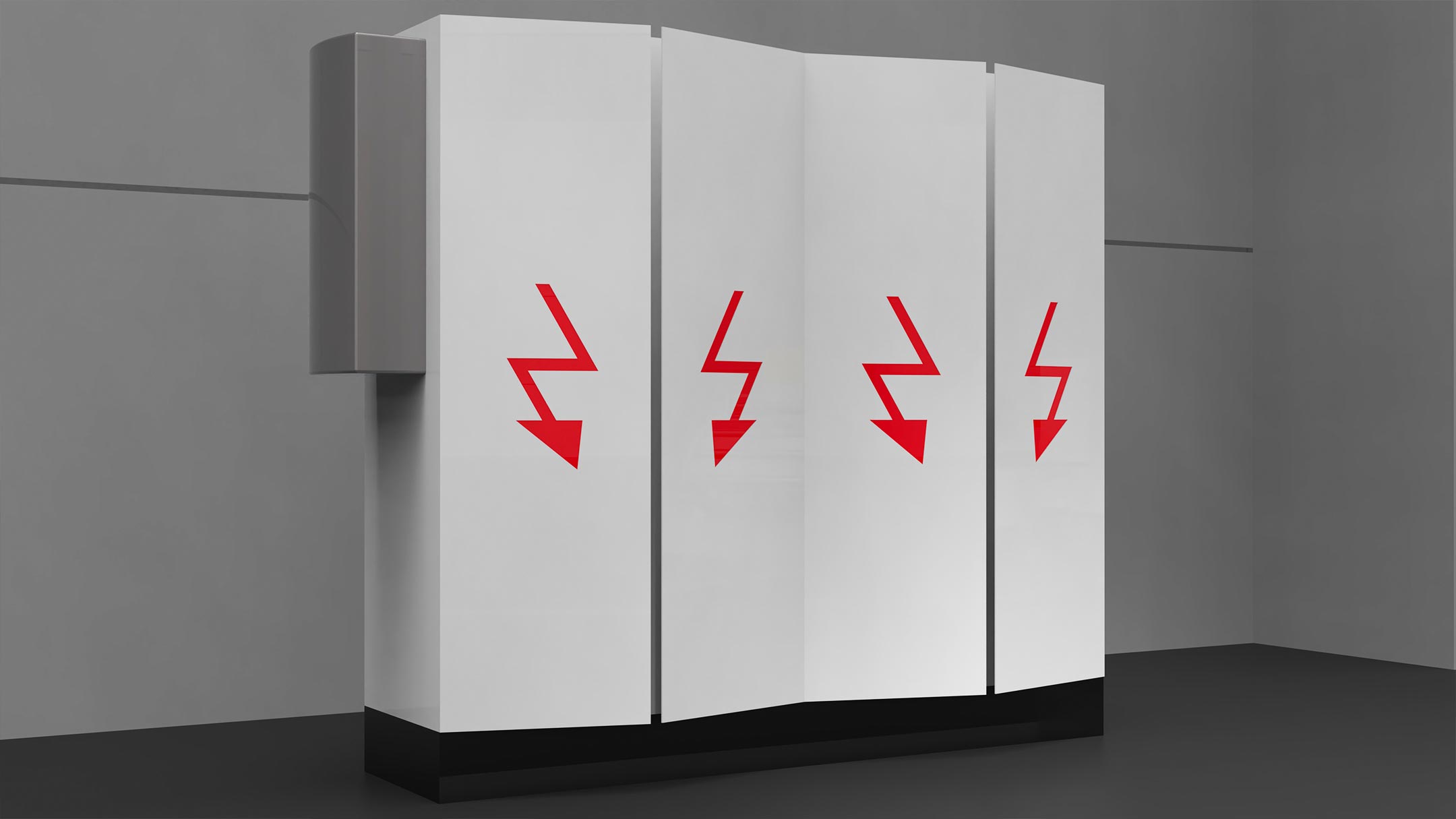
4.3 Electrical cabinet
Switch cabinet for housing components, cabinet type with base and blind doors, complying with CEI EN 60204-1. standard cable length 10 m, longer lengths at extra charge.
Standard supply:
- General line disconnector
- Pelv control circuit – 24 VDC
- Artificial ventilation to ensure the proper functioning of the electronic equipment contained therein
- Terminal blocks for connecting field components
- Components marked and numbered as per circuit diagram
- IP54 degree of protection
- Diagram pocket
- 230 V AC service socket inside cabinet
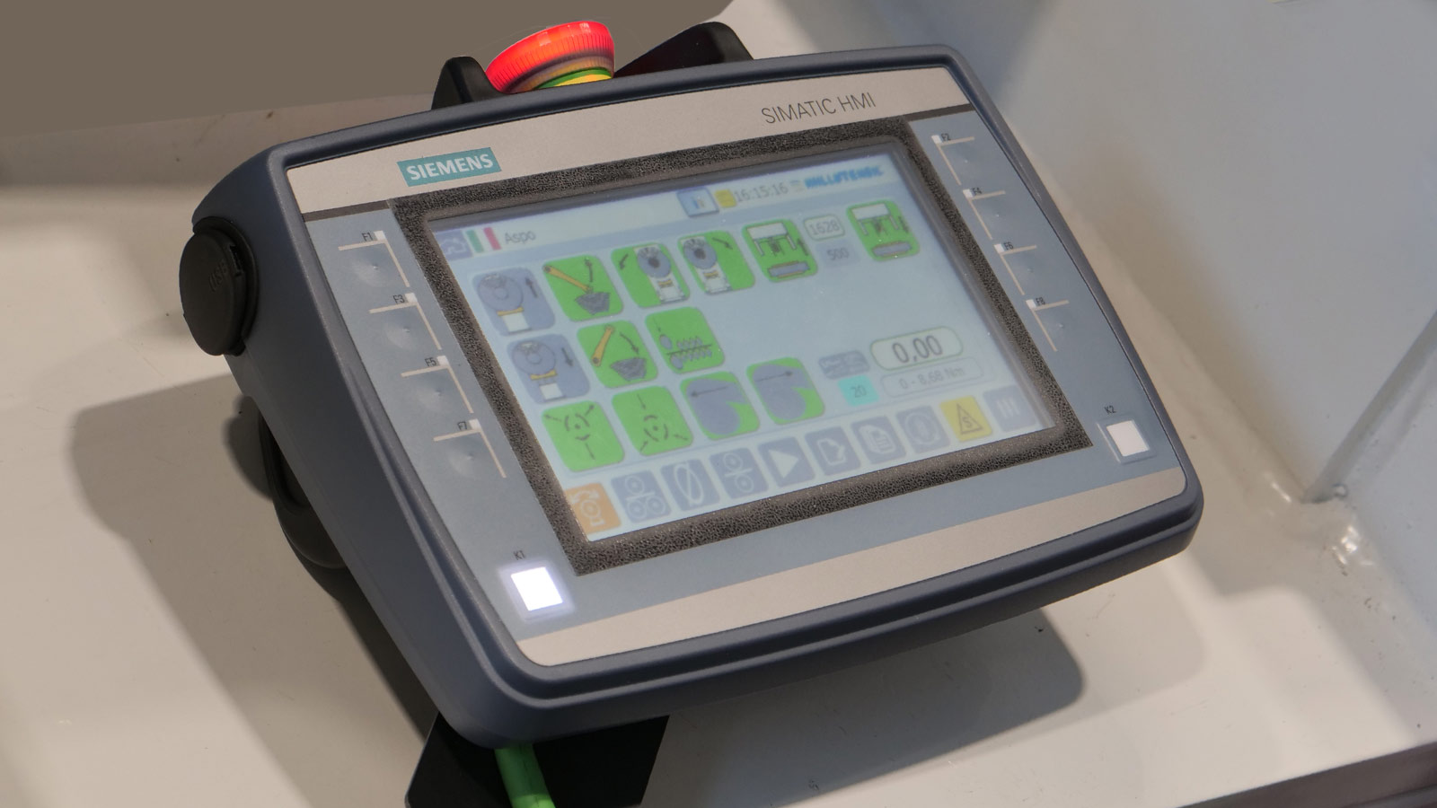
4.4 Human/machine interface with mobile control panel
The mobile control panel enables easy access to all functions of the line. A highly intuitive user-friendly graphical interface makes all operations easily manageable. Equipped with a long cable, it allows the operator to position themselves conveniently in front of the component in use.
These are the features:
- Siemens touch screen
- Colour graphics and movements with symbols
- IP 54 degree of protection
- Profinet network connection
- Tiap programming software
- Multilingual
- Working recipes
- Mould code stored on a memory card
- Cable length 10 metres
4.5 Online tele service with Ewon card
The online teleservice with Ewon card enables remote monitoring and maintenance capabilities. Through this system, technicians can access the equipment’s diagnostic data and troubleshoot issues from a remote location. This functionality enhances efficiency by allowing for quick response times to any potential issues, minimizing downtime and optimizing production processes. Additionally, it provides the flexibility for experts to provide support and guidance regardless of geographical location, ensuring uninterrupted operations and maximizing equipment uptime.

5. Accessories
5.1 Line safety barriers
Line safety barriers are a crucial accessory in any industrial setting, prioritizing safety and mitigating potential risks.
Comprising protective wire mesh, these barriers offer enhanced visibility while effectively delineating danger zones. Their appropriate height ensures optimal containment, minimizing the risk of accidents or injuries.
Equipped with access doors controlled by electric locks, they provide controlled entry and exit points, further enhancing safety measures.
Additionally, push-buttons with opening requests enable authorized personnel to access restricted areas, ensuring compliance with safety protocols.
VR 360°
Click and drag to rotate the view. Scroll to zoom.
LAYOUT
All the advantages of choosing Millutensil

With a single click, you will manage a complete line made up of several machines, e.g. decoilers, straightening machines, shears, welding units and accessory equipment, such as conveyors and lubrication systems.

Thanks to the Smart Link System all the systems are interconnected to provide an accurate and optimized process.

This programme allows great saving of time for the reset of the line and of all the parameters for production changes.

All the systems included in one single integrated system allowing a single line certification management.
Our wordlwide references

Office: Corso Buenos Aires, 92 – 20124 Milano – Italy Tel. +39 02 29404390 – Fax +39 02 2046677
Plant: Via delle Industrie, 10 – 26010 Izano (CR) – Italy – info@millutensil.com – millutensil.com