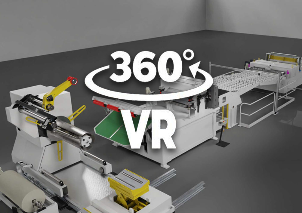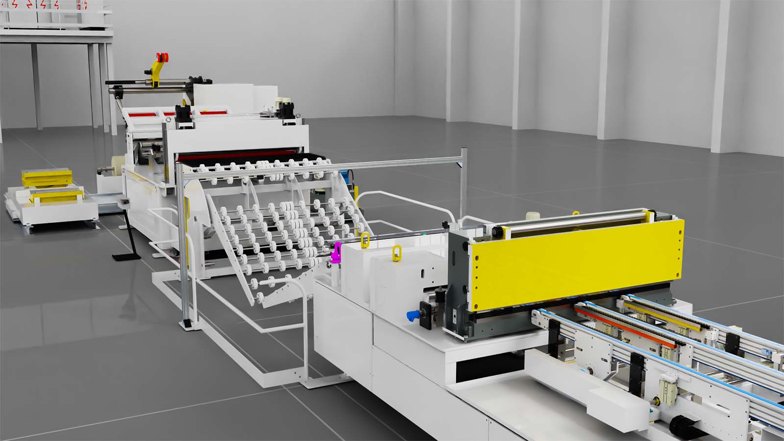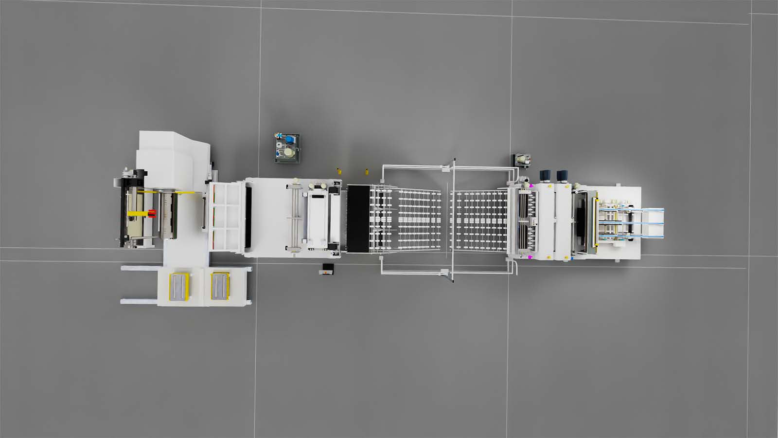
STRIP FEEDING LINE IN LONG CONFIGURATION FOR 10000 KN SERVO PRESS
According to Layout 054.904.02928
Projects Traunreut and Wroclaw
-Supporting structure made of welded steel, widely dimensioned
-Spindle shaft supported by double roller bearings
-The expansion and closing of the spindle is carried out by wedges with hydraulic movement.
1.1 Lateral translation for coil alignment
1.2 Snub arm
Integrated in the upper part of the decoiler, moved by means of a hydraulic cylinder, it is sized to contain the materials during insertion. The wheels coated with polyurethane allow not to damage the surface of the material, the movement is activated by the control panel
1.3 Conical lateral guide
Integrated in the upper part of the decoiler, oriented at 10 o’clock, the insertion movement takes place by means of a hydraulic cylinder, the width adjustment is motorized at height with the possibility of storing the position in the recipe. The lateral conical guides ensure the containment of the coil
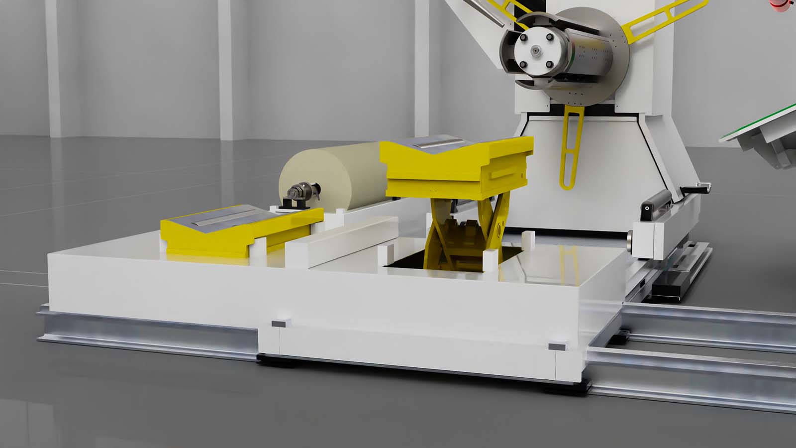
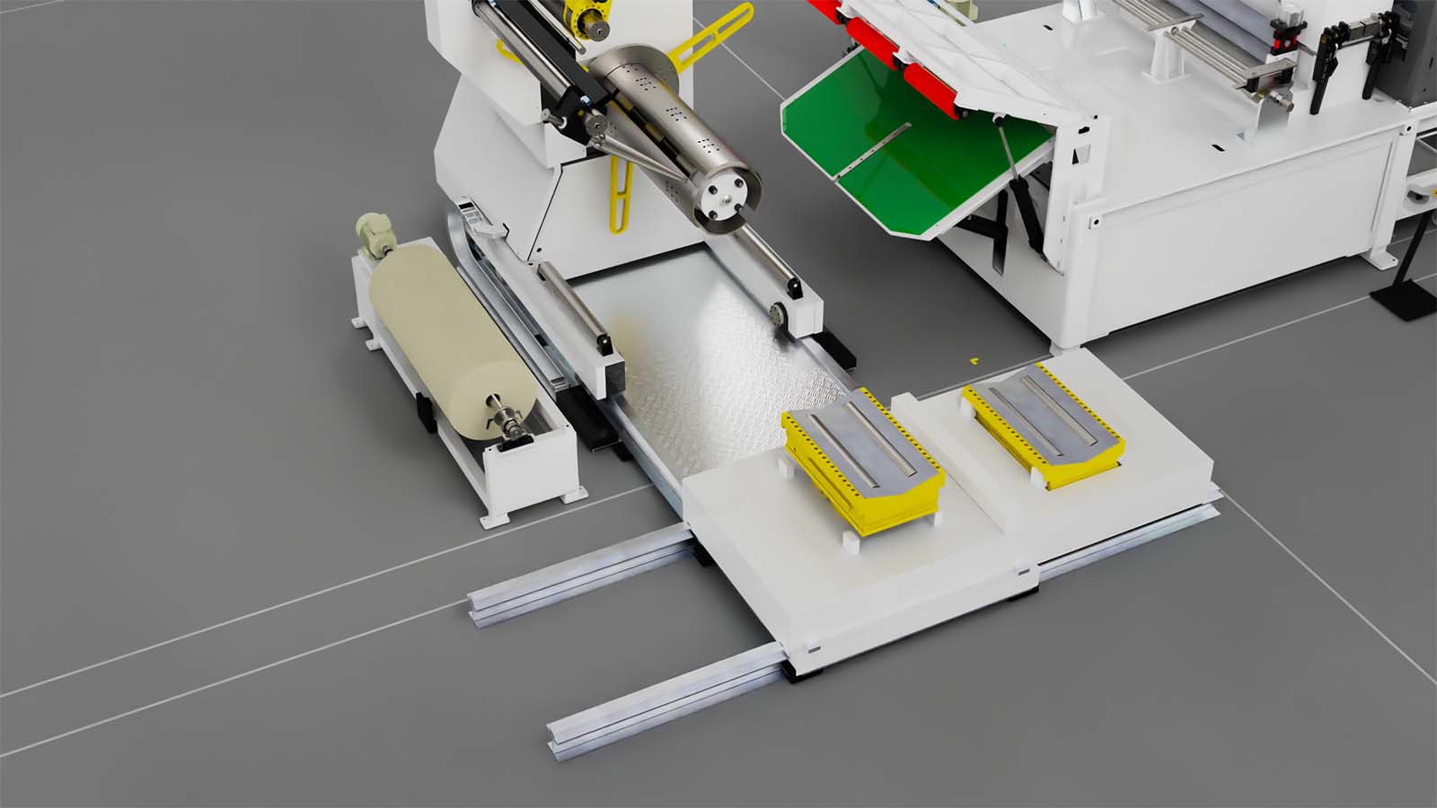
1.4 MOVABLE COIL CAR – multi-cradle CMC
Consisting of:
Movable coil without “V-Shape” saddle
-Electro-hydraulic drive
-Motorized horizontal translation by means of wheels on floor rails
-Loading cradle with motorized lateral translation by means of floor
rail with multi-saddle “V-shape”
Covered with polyurethane to avoid damaging the strip coil containment arms. They are used to block the narrow coils lying on the cradles laterally so that they cannot fall during translation
1.5 Paper recoiler
Positioned at decoiler base
Driven by gearmotor managed by
“Inverter” frequency converter
With “book-type” head opening via two hydraulic cylinders for
strip beginning insertion.
-Motorized overlapping pinch rollers placed at the entrance with
pneumatic opening and closing of the upper pinch rollers
-Motorized lower straightening rollers
-Upper idle straightening rollers contained in a weighing monobloc
-Block adjustment of the upper straightening rollers through
motorized mechanical jacks with quota display on the touch panel
-All rollers can be disassembled individually for accurate maintenance
or for replacement.
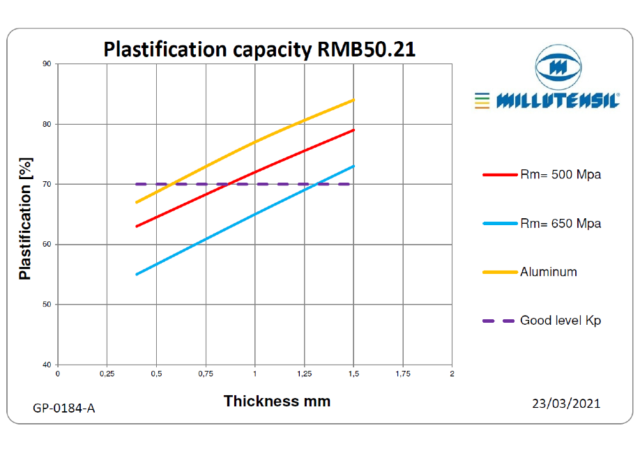
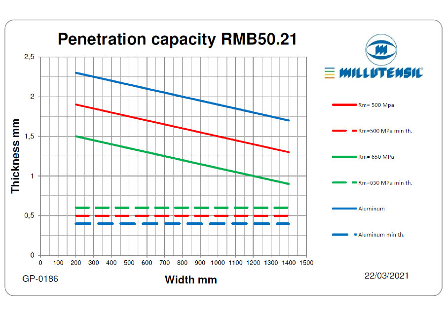
2.1 Strip guide
Positioned at the entrance, the rollers allow to keep the belt guided during the feeding of the material.
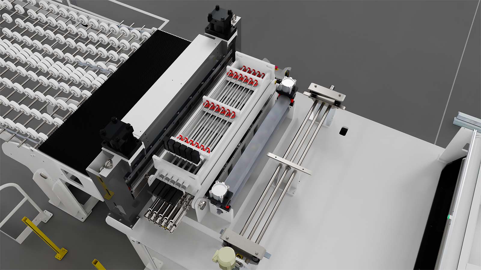
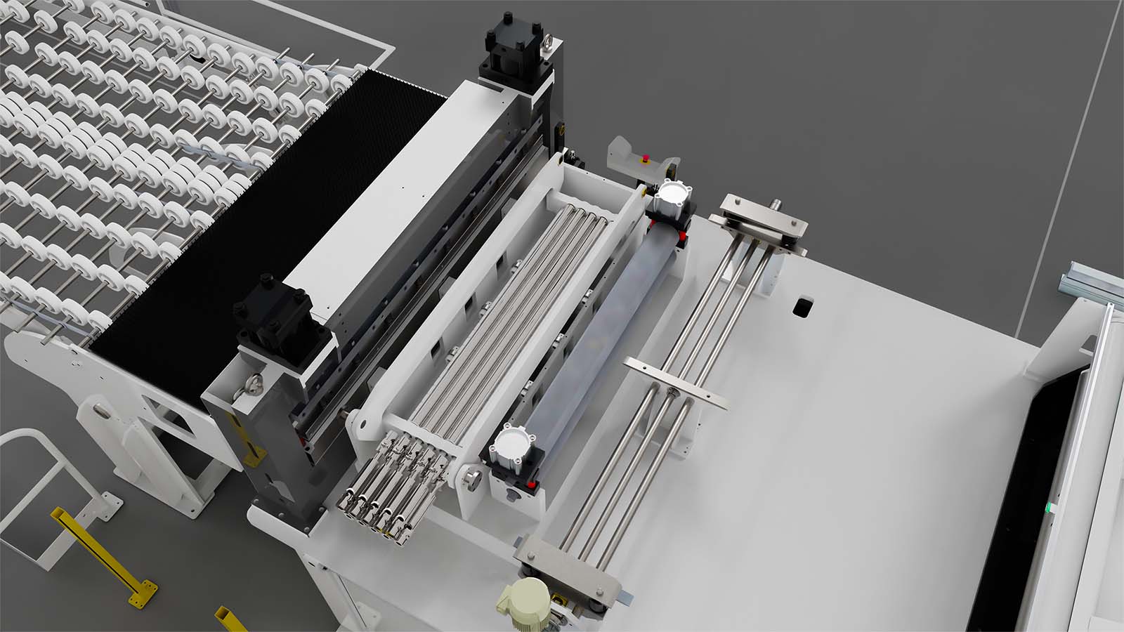
2.2 Hydraulic threading table for strip beginning
to help strip insertion coming from the coil. The upper deflector roller facilitates the containment of the material bending while the extension of the table facilitates the removal of the sheet of the different diameters of the coil.
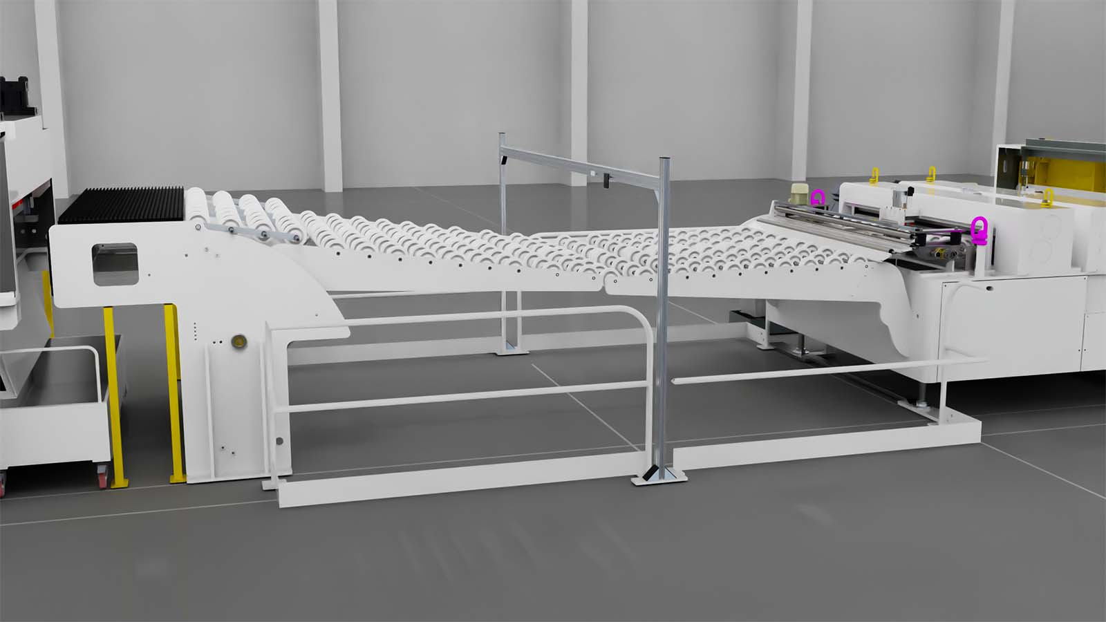
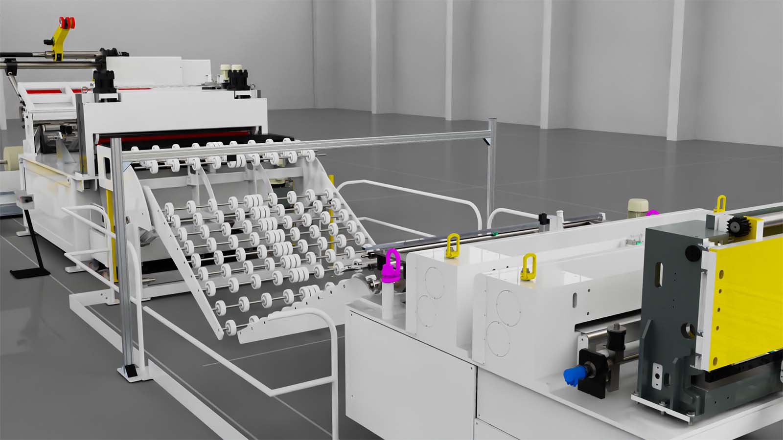
2.3 Feed-in table
located in the loop creation area, between the straightener and the
feeder, it can be raised hydraulically in height to reach the pass line
and create a connecting bridge that allows the operator to
accompany the strip between the two machines without handling
the material by hands
2.4 Fixed Base with fixed height
2.5 Loop control
Duly sized structure positioned astride the loop. The necessary controls are applied to the support to manage the lung of material between the straightener and the feeder allowing the machine positioned upstream of the line to follow the production continuously without stopping
2.6 additional carpentry (structural steelwork – space) for coil cleaning unit
To be placed before the straightener
(provided by BSH)
2.7 additional carpentry (structural steelwork – space) for plastic foil
To be placed before the straightener
(provided by BSH)
2.8 additional carpentry (structural steelwork – space) for marker
(provided by BSH)
2.9 operator platform
To allow the cleaning of the straightening rollers
it is placed after the straightener
- 4-edged cutting blades
- electro-hydraulic drive
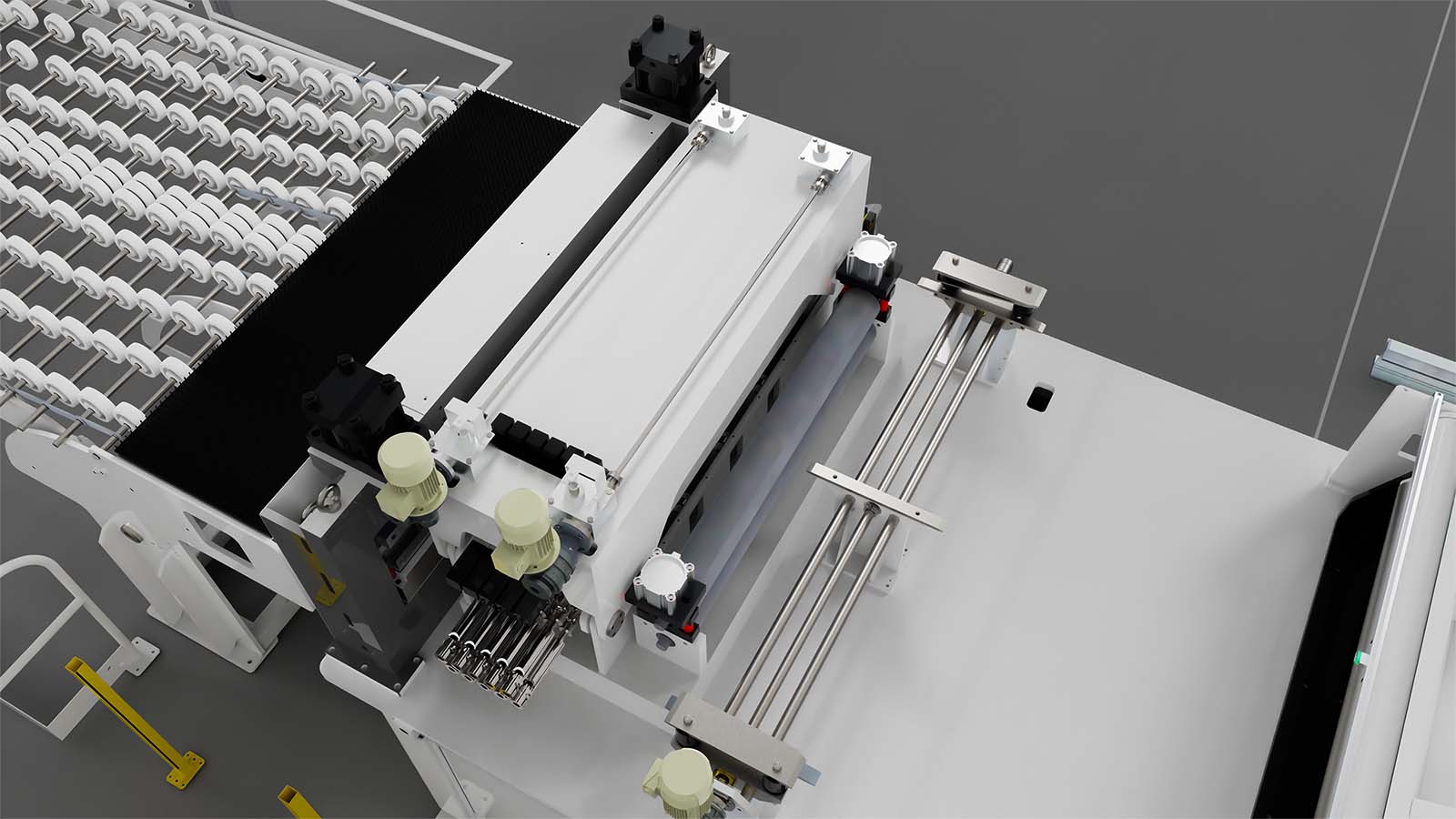
Electro-welded structure containing the overlapping rollers
Upper roller opening through 2 synchronized cylinders through
torsion bar.
-Manual adjustment of the stroke pressure
-Micrometric manual adjustment of the stroke of the upper/
lower cylinders upper roller to avoid excessive pressure on thin and delicate materials.
-Upper roller opening of the feeder to allow stretching
of the strip for pilot centring of the dies during blanking by means
of Schmidt joint
-Infeed roller conveyor for loop with strip detecting sensor
-driven by 2 Brushless motors with direct transmission by means of precision gear motor without gap
4.1 Strip guiding
Mounted on the entrance. The rolls allow the guiding of the strip during the
feeding of the material.
4.2 Strip locking clamp
Pneumatic system with negative instantaneous type of operation by means of springs, positioned before the feeder rollers, allows the strip to be clamped during sudden emergencies of the line avoiding the sheet go backwards causing it to fall down
4.3 Encoder wheel
Placed at the exit of the feeder, it checks the quota set in the recipe by stopping the system in case of non-positioning.
The line has two operating modes that can be set at choice and stored in the recipe, A) motor resolver B) metric wheel
4.4 electro-welded base-frame to fix the feeder to the press
-With height adjustment by screw jacks
controlled by gearmotors
With Quota Display On Touch Panel
4.5 feeder lateral translation for rolls cleaning
4.6 Additional carpentry (structural steelwork – space) for spray lubricator
To be placed after the feeder
(provided by BSH)
4.7 Additional carpentry (structural steelwork – space) for second feeder
it is placed after the feeder
- 4-edged cutting blades
- electro-hydraulic drive
- For transporting cut sheet metal coming from the electric shear
- dimensions sheet width max mm. 1400 min. mm 400
- sheets per minute 32 parts/min.
- electromagnetic conveyor belts with toothed belts in
- polyurethane for transporting sheet metal.
- n.3 conveyor belts, width 32 mm, length 3100 mm
- the transversal adjustment of the lateral conveyor belts carried out by means of operating screws controlled by a gear motor with encoder program (die code)
- central conveyor belt with fixed position for sheet metal support
- the motorization of the 3 conveyor belts takes place by means of a servo-ventilated three-phase asynchronous motor
- pneumatic belts-saving coming out of the shear to support the sheet during the cutting phase
- nr. 1 starting station with retractable pneumatic stops for sheet metal stop internal shear
- n.1 intermediate station with “retractable” pneumatic stops for stopping sheared sheet metal
- n.1 final station to take sheet metal with side compactors, pneumatic for sheet cantering with “retractable” pneumatic stops with motorized length adjustment.
quota control via encoder (die code) - conveyor belts positioned on the line basement, adjustable in height with quota control (die code) motorized height adjustment
h = 1240 mm reg. +/- 100 mm
02001-Automation System TAS 1
AUTOMATION SYSTEM CONSISTING OF:
1.HMI WITH MOBILE PANEL KTP700F SIEMENS TOUCH SCREEN 7” COLOURED – L=10 M
PROGRAMMING SOFTWARE TIAP
1A.COLOURED FIXED TOUCH PANEL TP 1200 SIEMENS 12” OPTIONAL
2.PLC SIEMENS IM151F FOR COMMAND LOGIC
3.SAFETY MANAGEMENT INTEGRATED IN THE PLC
4.ON LINE TELESERVICE WITH EWON CARD
5.COGWHEEL ENCODER STANDARD UE FOR
SHEET EFFECTIVE DISPLACEMENT READING
6.CAM POSITIONER FOR ELECTRONIC CAMS
FUNCTION (OPTIONAL)
7.SERVO-DRIVE SIEMENS
8.SERVO-MOTOR BRUSHLESS WITH INTEGRATED
SIEMENS RESOLVER
7.1 Hardware equipment:
• clean contacts input for cams start feeder, pilots and auxiliary
as option “cam positioner” integrated in the receipt for electronic cams functions
• clean contacts input for auto consent from the press
• sheet presence input sensor configuration and compressed air sheet presence sensor
• clean contacts outputs for auto-run signalling, end-stroke, pms press stop, tool press stop and auxiliary cam
• contacts input and output for the obligatory safety functions (emergency and fences)
7.2 Software characteristics:
• operator program management “receipt” type, directly on the mobile panel for setting of all
functioning parameters (acceleration, deceleration, speed, stroke, repetition, cycle, etc.)
• it is possible to manage 500 receipt with 20 different steps for each receipt and 100 repetitions each
• complete diagnostic of the anomalies by means of alarms displayed and silenced
• setup of single step length in decimal metrical (0 up to 9.999,99 mm)
• display of value reached.
• functioning in automatic cycle, single or continuous
• manual movements jog+/jog- and single test stroke to reduced pre-set speed, with quota display
• pieces decrease counter
• start/stop auto-cycle form the panel
• sheet displacement control with resolver
• as option, effective sheet displacement measurement by means of cogwheel encoder
• panel and relevant programming instruction in end-customer’s language
7.3 Electric panel / cabinet
• electric cabinet for components housing, cabinet type with base and blind doors, confirming norm cei en 60204-1. standard cable length 10 mt. longer cables have overprice
• main line switch
• control circuit pelv – 24 vdc
• artificial ventilation suitable to grant the correct functioning of
• the electronic devices
• junction box for the connection of the field components
• signed and numbered components according to electric diagram
• protection grade ip54
• diagram holder pocket
• service socket 230 vac inside the cabinet
7.4 Man/machine interface with mobile control panel touch screen Siemens
• colour graphic and movements with symbols
• protection grade ip 54
• net connection to profibus/profinet
• programming software tiap
• multilanguage
• working receipt
• die code stored in a memory card
• cable length 10 mt
7.5 remote pushbutton for decoiler management
7.6 stationary control touch panel
7.7 online Teleservice with modem card or ewon
7.8 Unlimited remote assistance service for short support requests
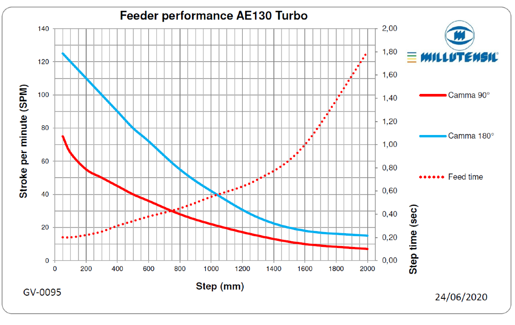
8.1 Electronic Turbo Feeder for Aluminium
Electro-welded structure containing the overlapping rollers
Upper roller opening through 2 synchronized cylinders through
torsion bar.
-Manual adjustment of the stroke pressure
-Micrometric manual adjustment of the stroke of the upper/
lower cylinders upper roller to avoid excessive pressure on thin and delicate materials.
-Upper roller opening of the feeder to allow stretching
of the strip for pilot centring of the dies during blanking by means
of Schmidt joint
-Infeed roller conveyor for loop with strip detecting sensor
-driven by 2 Brushless motors with direct transmission by means of precision gear motor without gap
Encoder wheel
Placed at the exit of the feeder, it checks the quota set in the recipe by stopping the system in case of non-positioning.
The line has two operating modes that can be set at choice and stored in the recipe, A) motor resolver B) metric wheel
8.2 Line safety fences
consisting of black metal protection nets to allow better internal visibility, appropriate height depending on the area affected by the dangers, complete with access doors controlled with electric locks equipped with buttons with request for opening.
Light barriers are positioned in some points of the line
8.3 Millutensil pack “Industry 4.0 ready”
– Network analyser for monitoring energy consumption
– Gateway for industrial iot applications through applications with protocols of
cloud downloadable from yocto linux
Please notice: the quotation refers only to the hardware part.
as regards the software, the cost is a function of the quantity
of information you want to exchange via the gateway.
8.4 Installation – start-up and training:
foreseen 20 working days + travelling days with 2 technicians with assistance from technicians.
Note: any extra days not depending from Millutensil will be charged at the price of € 840 per day per person
8.5 To attend during production
foreseen 5 working days + travelling days with 1 technician
with assistance from technicians.
8.6 Additional warranty +12 months total 24 monhs
8.7 Transport DAP DE
8.8 Transport DAP PL
VIDEO
All the advantages of choosing Millutensil

With a single click, you will manage a complete line made up of several machines, e.g. decoilers, straightening machines, shears, welding units and accessory equipment, such as conveyors and lubrication systems.

Thanks to the Smart Link System all the systems are interconnected to provide an accurate and optimized process.

This programme allows great saving of time for the reset of the line and of all the parameters for production changes.

All the systems included in one single integrated system allowing a single line certification management.

Office: Corso Buenos Aires, 92 – 20124 Milano – Italy Tel. +39 02 29404390 – Fax +39 02 2046677
Plant: Via delle Industrie, 10 – 26010 Izano (CR) – Italy – info@millutensil.com – millutensil.com

